The Hidden Cost of Post-Processing
DfAM is the key to reducing post-processing burden.

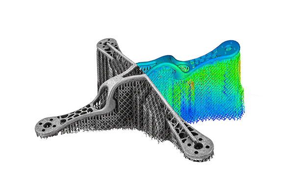
Simulating the print process using Materialise software. Image courtesy of Materialise.
May 2, 2023
In additive manufacturing (AM), post-processing is the required work to get a printed part ready for deployment. This work can range from removing the support structures that keep the part in place during the printing process, to additional milling operations to produce high-quality surface finishes. Although most of the printing process has been automated, post-processing still relies on “conventional finishing methods,” according to Mohsen Seifi, vice president of global advanced manufacturing programs, ASTM International.
In his forward to “Wohlers Specialty Report on Post-Processing: Final Steps of AM Part Production” (second edition, 2023, Wohlers Associates), Seifi writes, “It is commonly understood that the time and cost to perform post-processing is high. It is even higher in some cases than the actual time and cost of printing the part itself.”
The cost of post-processing is significant enough that it has spawned a market of its own. Dye Mansion, counting over 400 customers worldwide, says, “We are the global leader in post-processing solutions for industrial polymer 3D printing that turns 3D-printed raw parts into high-value products. From perfect fit eyewear to personalized car interiors, our technology makes 3D-printed products become a part of our everyday life.”
Dye Mansion’s offerings include industrial machines for cleaning, surfacing and coloring 3D printed parts. Other companies such as AMT, AM Solutions and Quill Vogue also offer post-processing equipment.
To identify the hidden cost of post-processing, we delved into the 65-page Wohlers report and spoke to Roy Sterenthal, VP of additive manufacturing at Oqton. While post-processing may be unavoidable, there are ways to minimize it. The key is in the design phase, where you can employ Design for AM (DfAM) strategies to ensure the part can be deployed with little or no post-processing whenever possible.
Costly Support
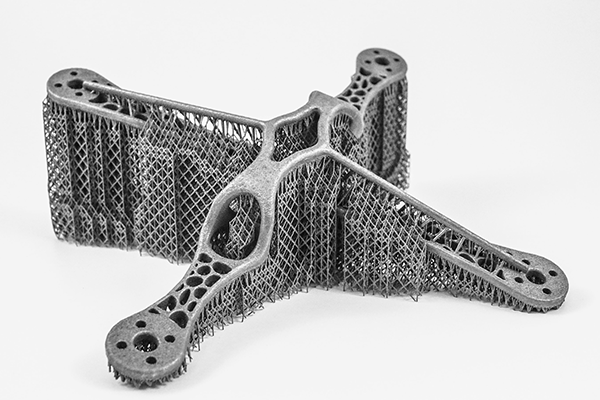
Support material is a pesky AM necessity. It can be a scaffold-like structure that secures the desired part in the print chamber during the print process. Removing it afterward comes at a cost, in the form of labor and time.
The report from Wohlers Associates notes, “With material extrusion (MEX) and vat photopolymerization (VPP), the [support] material is attached to the parts being produced. With powder bed fusion (PBF) and some binder jetting (BJT) processes, the material is in the form of unattached powder in and around the parts. In all cases, the support material must be fully removed, sometimes manually.

“Sometimes the removal is done manually. Sometimes it’s done with a machine. After that, you might need to use machining to get better surface quality, definitely for the areas where you had supports,” notes Sterenthal.
The Wohlers report points out, “Most AM parts have a rough surface finish where the supports were removed. It can be improved by sanding, grinding, shot peening and/or machining.”
Guy Zimmerman, chief marketing officer of Xjet, says, “There are two major post-processing cost drivers: Removing support structures and powder from inner cavities and structures, and machining and polishing to achieve accuracy and surface roughness. Both issues are basically eliminated when utilizing powderless direct material jetting technology, like NPJ of Xjet.”
In some systems, the support structure and the desired piece are printed with the same material, in a way that’s easy to break off. In others, the support structure is printed with a different material, usually much weaker than what’s used for the primary part. In both cases, someone would need to manually remove them using hand tools.
According to Wohlers, “Breakaway support materials require an MEX system with dual print heads. It can result in parts with a better surface finish compared to a single-material system.”
Support removal might be a multi-step process that begins with the manual removal of the primary structures, followed by washing away or dissolving the rest. In complex designs with lattice structures full of canals, crevices and pockets, trapped material removal can be quite a challenge.
Zimmerman advises, “Choose the right technology for the relevant part characteristics and design requirements. If you are looking for large, massive parts with relatively low accuracy, then SLM may be a solution that will reduce post-processing. If you need complex structures, accuracy and low surface roughness, you should choose powderless technology that can deliver the above with almost no post-processing.”
A HIP Treatment
With metal AM, the printed piece may require a hot isostatic pressing (HIP) treatment. Think of it as cooking the piece in a special oven, under high heat and pressure, to make it more durable.
The report from Wohlers Associates explains, “HIP eliminates internal and surface porosity of parts. Voids are removed, resulting in improved density and mechanical properties. The metallurgical properties of AM parts after HIP can resemble wrought and forged metals.”
With some pieces, after the HIP process, you may also need a computed tomography scan to ensure the heat hasn’t deformed the critical internal structures.
“You cannot see things like internal channels, so you want to make sure they turn out correctly,” says Sterenthal.
Designing for AM
Oqton develops a cloud-based manufacturing execution system. Sterenthal describes Oqton as a comprehensive platform that covers order management to workflow tracking.
Part of Oqton is a design software package called 3DXpert, integrated additive manufacturing software to streamline the workflow from design to printing.
“One aspect of 3DXpert is DfAM. We have developed specific capabilities and applications based on our lattice engine and implicit design technology,” says Sterenthal.
DfAM is a design methodology. It promotes the use of AM-efficient topology in the design phase to prevent potential hiccups and to minimize the post-processing burden. It’s based on the general principles that AM experts have uncovered. Programming these principles into the software’s design rules makes it easy for novices to design for AM.
“How do you know how many parts you can put on a tray? That’s a big question. From a design point of view, you want to know the best orientation for your part. Instead of a T-shaped part, you could design it with chamfers so that the part doesn’t need support structures. You can also avoid thin walls that are below the printer’s specification,” says Sterenthal.
“A good software should give you a build simulation. This is the technology that simulates the entire print job. This gives immediate feedback on whether you’ve designed the support structures correctly, if they will hold up, if the part will deform, and if you need to compensate for the deformation,” he adds.
Optimal orientation can help fit the greatest possible number of parts on the print tray or in the print chamber, increasing the output and cutting down on the print time. Integrated simulation features can also reveal how the print job will be executed, step by step, exposing issues such as thin walls and potential deformation. Designing a part to reduce the need for support structures, and heat treatment, and surface refinement are all part of DfAM, specifically aimed at reducing post-processing. They contribute to stronger parts and quicker printing.
Wohlers Associates’ report advises, “The best way to minimize the cost and time of post-processing is to follow robust DfAM practices. DfAM also greatly helps to improve the quality and functionality of your parts. As more industries adopt DfAM in a more systematic way, the percentage of cost associated with post-processing will decline.”
More ASTM Coverage
More Oqton Coverage

Subscribe to our FREE magazine, FREE email newsletters or both!
About the Author
Kenneth Wong is Digital Engineering’s resident blogger and senior editor. Email him at [email protected] or share your thoughts on this article at digitaleng.news/facebook.
Follow DE


