Latest News
December 1, 2008
By Jeff Waters and Ruben Bons, Sr.
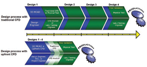
 With a well-conceived implementation plan, upfront CFD can deliver major time-to-marketsavings and quality improvement to your company. |
The mid 1990s brought a radical divergence in the CFD world. Traditional simulation tools built for PhD-level analysts remained popular, but a new category of “upfront” engineering products gained ground by targeting multi-tasking design engineers without specialized CFD knowledge.
Upfront CFD enables these non-specialists to quickly make selections based on hundreds of design options. As the best design directions emerge, engineers can include additional detail and move toward a more rigorous, quantitative simulation phase akin to traditional CFD. The real business benefit, however, lies in the early phase.
The Human Factor Is the Key
After choosing and procuring an upfront CFD tool, many companies expect it to magically generate an immediate ROI. Without a well-conceived implementation plan, however, even the easiest of tools will soon gather dust. As with almost every new initiative, the biggest factors in success have nothing to do with technology or software features; human factors are the key. In this case, there are four imperatives for successfully implementing upfront CFD for design engineers.
The first is to provide adequate training. It sounds obvious, but this is a simple mistake that many companies make. These tools are marketed based on ease of use, companies often equate that with “no training required.” Imagine if the same thought process had been applied to a company’s MCAD tool.
|
It is important to train all the engineers who might need to use these tools. Since upfront CFD is often used sporadically, it might be effective to provide touch-up training every six to 12 months.
Secondly, beware of the non-specialist specialist. Early-stage technologies provide the best benefit when implemented throughout the engineering team. Besides avoiding the risk of “expertise walking out the door,” a thorough implementation will enhance the entire group’s efficiency and innovation, reinforcing a regular cycle of use.
Many companies identify a single design engineer to shoulder all upfront CFD responsibilities. Others train the entire team and wait for individuals to show an interest. The result is usually the same in both cases: A single member of the design team gets targeted as the group specialist. That creates the same bottlenecks inherent with the traditional specialist model.
The third imperative is to build upfront activities into your official process. If you typically track and manage projects with Gantt charts and gate review systems, build upfront CFD milestones into the plan.
Finally, upfront CFD tools are best used to evaluate many, rather than a few, design options at the conceptual stages. Dozens or hundreds of potential directions can be compared to quickly choose the right places to focus engineering effort.
The central idea of exploring a large number of options is often missed by new adopters. Many wait to use the upfront design tool until the late design stages, after most decisions have already been made. The tool ends up being used for design verification instead of design direction and has little impact on the overall project timeline or innovation. Upfront CFD is all about doing more now…and less later.
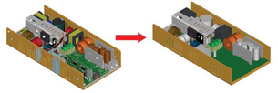
 Initial CFD simulations shown here on a geometrically simple, but representative, model. On leftis the detailed model; on the right, a simplified model for upfront CFD. |
Best Practices and Tech Strategies
Once an early-phase CFD tool is in place and all imperatives met, it is time to start using the tool to maximum benefit. Here are some tips:
Start with a sketch: Before any simulations, sketch a conceptual model with the most important geometry and indicate the fluid and heat-flow paths. This can be done with a rough CAD model and notation added (arrows) to indicate anticipated airflow.
Sketching at this stage forces team members to think about the physical phenomena in play and ask themselves key questions like, “What factors are most important to the system?” and “What am I missing?” Addressing these types of questions leads to more accurate and efficient simulation models.
At this stage you should also understand critical physical effects. If the fluid is a gas, are compressibility effects significant? If the fluid is a liquid, do you expect any phase change such as solidification or cavitation? Do you expect the flow to be laminar or turbulent? The answers and results from related test data, experience, and hand calculations will help you determine realistic result ranges.
Classify your assumptions: Every calculation you perform is founded on certain underlying assumptions; upfront CFD is no different. It is important to understand if your assumptions are conservative or non-conservative in relation to critical results such as the peak chip temperature, total flow through the system, and pressure drop in the system.
Typical flow assumptions include incompressible or compressible, laminar or turbulent, and slip or no-slip wall conditions. Typical thermal assumptions include perfect thermal contact, radiation or no radiation, adiabatic external walls or external leakage.
In a heating situation, for example, assuming perfect thermal contact is a non-conservative approach. Any contact resistance between two parts (which inevitably exists in real life) will cause actual temperatures to be higher than predicted by simulation.
Keep it simple at first: Make your first simulation on a geometrically simple but representative model of your system. Start with a relatively coarse mesh, but seek to include all the significant physical effects. This is most important for new designs or if a team is just beginning to use the analysis tool. The major reason for this is purely pragmatic: When you make mistakes (which everyone does) you want to see the effects quickly and clearly. With a simple model, you will be able to process results and move on to other scenarios much quicker.
 A typical fan curve plot. |
Upfront CFD in Action
Consider this example of internal forced air cooling.
Start by keeping any components in the CAD model that are significant to the air-flow path, form part of the heat-flow path, or are significant heat generators. Consider both the total heat the components dissipate and their heat-per-unit-volume power density.
Generally apply 0psi (gauge) pressure to all atmospheric inlets and outlets. Do not, however, apply a pressure to any inlets or outlets where you are also specifying a fan, velocity, or flow rate. Doing so overspecifies the solution and typically causes CFD solvers to diverge.
Be sure to specify ambient room temperature or incoming line temperatures at all inlets and assign volumetric heat sources to the significant heat-generating components. If heat leakage through housing or case walls is significant, assign a film coefficient to the exterior faces of the enclosure. This approach saves analysis time by avoiding the need to computationally model the surrounding air. For natural convection, 5 to 10 W/m2-K is a reasonable choice. If the external air is a forced flow, use Nusselt correlations to get an estimate. Analyze your simple system with double, and half that film coefficient to get a handle on best- and worst-case effects.
Finally, assign appropriate fan curves. Most companies try to use the same fan part number across multiple designs to save material and development costs. Fans produce more or less airflow depending on the geometry of the systems on which you attach them. It is worth your time to verify fan curves provided by the manufacturer in your own lab. You may even need to come up with your own curve that better matches reality.
Upfront CFD can radically reduce product-development time and cost when rationally implemented as a core competency throughout the design engineering department. With a little training and a pragmatic approach, upfront CFD offers major gains in productivity, innovation, and first-time quality.
More Info:
Blue Ridge Numerics
Charlottesville, VA
Jeff Waters is an account executive with SpaceClaim Corp. Previously he worked at Blue Ridge Numerics, helping manufacturing and product development companies efficiently implement upfront CFD. He is a graduate of Rose-Hulman Institute of Technology and began his engineering career at General Motors, where he introduced a variety of specialty and early CAE technologies for simulation-based stress, strain, thermal and flow R&D. Send comments about this article to [email protected].
Subscribe to our FREE magazine, FREE email newsletters or both!
Latest News
About the Author
DE’s editors contribute news and new product announcements to Digital Engineering.
Press releases may be sent to them via [email protected].


