Latest News
November 1, 2004
By DE Editors
ACUITIV Software Introduces Interactive Postprocessing CFD Visualization Solution
ACUITIV Software (Batavia, IL; acuitiv.com), provider of next-generation computational fluid dynamics (CFD) visualization software, is now shipping ACUITIV v4.0. Enhancements enable ACUITIV to deliver a fully interactive, enterprise-class CFD visualization solution for industries worldwide, including automotive, aerospace and defense, power, and chemical processing. 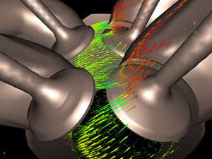
Built on ACUITIV’s architecture, which is based on VR Juggler and OpenGL, ACUITIV v4.0 provides customers with a suite of interactive tools for transient model visualization, multi-PC visualization sessions, and steady-state model support. Key features and benefits include the ability to read Fluent transient data sets plus an interactive tool suite for visualizing these complex data sets through the use of contours, isosurfaces, streamlines, and more. For information, visit acuitiv.com.
 ACUITIV v4.0 received the most votes in our August 2004 issue. Vote for your favorite from this month.
Wider Scanners Make Processing Large CAD Drawings Easier
Western Graphtec (Irvine, CA; graphtecusa.com) has added a half dozen 42 inch wide scanners to its stable. The new CS600 and CS500 series each include two 24-bit, full-color models. The IS200 series offers an 8-bit monochrome alternative. Each series offers a standard or Pro model, so users have the option to initially purchase a standard version and then upgrade to the advanced system later on.
The Pro models include interpolated resolution up to 4800dpi, as opposed to 800dpi for the standard models. The Pro models also incorporate a scanning with up to 40 percent faster throughput than standard models at comparable resolution settings. The CS600 and CS500 color scanners feature maximum scanning speeds of 9 ips (monochrome) and 3 ips (8-bit, 24-bit color) when scanning at 400dpi. In addition, they are compatible with the new industry standard sRGB color space. The IS200 also features a maximum scanning speed of 9 ips (monochrome, 8-bit graytone) when the scanning resolution is set to 400dpi.
All three series feature 600dpi optical resolution and utilize Contact Image Sensor (CIS) technology as opposed to common CCD scanning. And the CS scanners incorporate a sophisticated document handling system for effectively archiving old drawings, maps and various delicate graphic images electronically to prevent further deterioration and free up valuable storage space. The high-precision document feeding architecture also makes the CS scanners well log compliant, where continuous, long-length scanning is one of the mandatory requirements.
Scanning Master 21+ Driver software is included with all Graphtec scanners and facilitates scanner setup and control while also enabling easy post-scan editing, scan to file, and scan to copy operations. Each scanner comes with USB2/IEEE1394 dual communication ports and is accurate to ±0.1 percent (or ±5 pixels over the maximum scanning width).
E2E MACHINING Solutions Cuts Time and Cost in Component Machining
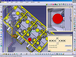
A new solution from Delmia Corp. (Auburn Hills, MI; delmia.com) called End-To-End (E2E) Machining Solutions is a suite of DELMIA applications that encapsulates activities found throughout the machining process from process planning to verification and inspection. Using DELMIA’s Process Engineer, a project is initialized in the conceptual product design phase, capturing logistical information such as location, labor, production shifts, production volume, and budgets. This data is then integrated with DELMIA’s Manufacturing Hub to facilitate all ongoing communication and collaboration. A rough skeleton process plan is thus able to be produced even before the 3D design data is available.
As the design is developed, all information is enriched and associated with the 3D information to generate models. Early access to machined models in the manufacturing cycle facilitates the entire process. Details on tool paths and tool changes are eventually added to the models, resulting in the NC code that drives the machines.
Using the simulation offering from DELMIA, manufacturers can quickly verify both parts and processes to reduce man-hours, increase machine utilization, and improve product and process quality. The process continues with virtual inspection to eliminate conflicts and offline programming of the CMM. Productivity is improved and time-to-market is reduced.
Opc Server Supports Meters and Controllers
The OPC Server from Omega (Stamford, CT; omega.com) is a hardware driver that has been written to a common standard, OPC or OLE for Process Control. OPC compliant programs (OPC Clients) for HMI, SCADA, DAS, and others, are available from Newport, Omega, Wonderware, Iconics, Intellution, Rockwell Automation, Inc., and National Instruments, among others.
The Omega OPC Server supports a wide variety of hardware including the company’s own iSeries meters, controllers and signal conditioners. Because the OPC Server is designed to work directly with these products, setup is simple, straightforward , and typically takes only a few minutes. The OPC Server also supports Omega’s EIS family of Serial Servers. With a Serial Server you can connect virtually any serial device or instrument to a computer through an Ethernet connection.
Price: $295.
Get the Project Team to Collaborate Right the First Time
CoCreate Software, Inc. (Fort Collins, CO; cocreate.com) has released OneSpace.net 2005, an online project data management and team collaboration solution designed so that engineers, suppliers, customers, and experts can work efficiently and effectively across a distributed project team. OneSpace avoids the jumble of databases, firewalls, e-mail attachments, engineering changes, and misunderstandings that often plague multi-site, contract, and outsourced project teams. Instead, it unites the “too many” into one place on the Web.
The program allows synchronization through web folders, providing a simple way to control, track, and version project data; and through enterprise systems, allowing access to product development data stored across multiple enterprise systems like ERP, PLM, and SCM without giving full access to proprietary company systems. And OneSpace.net 2005 is designed so companies working with supply chain partners can use a collaboration tool that flexes to fit their existing processes, rather than forcing their processes to change. Its new, out-of-the-box project templates support engineering change orders, working with suppliers to obtain bids, and coordinating with suppliers to take corrective action on sourced components. Project team members can now easily access template features such as light workflow with instant change notification. Because each company can configure the templates to fit its specific processes, team members can use and reuse the templates across future projects.
OneSpace.net 2005 clears the way for project success by helping users access the right version of their data from any location, view it in a meaningful way, and engage with their team members to coordinate ideas and changes. According to CoCreate, it puts customers on the fast track to delivering innovative products to market on schedule. For more information, visit onespace.net.
Vibro-Acoustic Modeler has Advanced Analysis
The latest version of the statistical energy analysis (SEA) simulation software from ESI Group (Paris, France; esi-group.com), AutoSEA2 version 2004, addresses higher frequency vibration and acoustic response of systems. It includes new capabilities like advanced SEA model building from CAD and finite element models, new load-case management functionality, a sound package modeler, and advanced predictive tools.
New model building and management features allow element-based creation of subsystems from finite elements or CAD models to reduce the amount of node-picking required to create subsystems. AutoSEA2 version 2004 speeds up model building and helps create more realistic models. It offers a load-case management feature so engineers can shift quickly through various operating conditions; and a sound package management module that enables automotive OEMs and suppliers to compare performance between two or more full-vehicle sound packages with the click of a button.
 Metris Introduces Its New Point-Cloud Platform
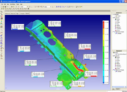
CMM-based laser scanning solution provider Metris (Santa Clara, CA; metris.com) has released Focus Inspection, its next-generation point-cloud inspection software. Focus Inspection is the first in a series of integrated tools built on the company’s new Focus V3 platform which, according to Metris, cuts point-cloud inspection time by 80 percent and offers 5x more throughput than its predecessor, CADcompare. While Metris earned its reputation in the automotive and aerospace industries, Focus Inspection is a stand-alone product, enabling it to serve in other manufacturing industries, such as sheet metal, castings, and ceramics.
Focus Inspection’s interface guides users step by step through the inspection workflow, with each step providing dedicated toolbars and icons. The software organizes data and results in a directory tree containing nominal, measured, and inspection data. This enables users to keep a logical overview when applying multiple inspection strategies on data. It also features scripting for process automation development and Microsoft Excel integration for reporting.
Metris plans to integrate all its software on the new Focus V3 platform. The Focus V3 suite will consist of three integrated primary products for scanning, inspection, and reverse engineering. Metris believes that Focus V3 will make it the first company to offer a completely integrated automatic laser scanning and inspection solution. For details, visit metris.com.
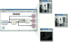 Image Processing Set Brings Model-Based Design to Embedded Vid Systems
The MathWorks (Natick, MA; mathworks.com) is shipping a new embedded video and image processing design tool. The Video and Image Processing Blockset helps imaging engineers in aerospace and defense, automotive, communications, consumer electronics, and other industries build models, simulate algorithms and system behavior, generate C-code, and verify designs, all within the Simulink environment, enabling model-based design for embedded systems development.
The MathWorks also expected to release an update of its Embedded Target for TI DSP by press time. It adds support for the TI DM64x development platform.
The new blockset provides a customizable framework for designing, simulating, implementing, and verifying video and image processing algorithms and systems. Its library includes 2D filters, conversions, geometric transformations, morphological operations, and transforms for rapid algorithm and system development. It is available for Microsoft Windows, Unix/Linux, and Mac. Price: Starts at $1,000.
Data Visualization and Analysis Improved
IDL 6.1 from Research Systems Inc. (RSI; Boulder, CO; rsinc.com) is said to build on the major themes of last year’s IDL 6.0 release, namely to make data visualization and analysis available to new users and to grow IDL functionality.
IDL 6.1 includes enhancements to IDL’s suite of iTools (iPlot, iSurface, iContour, iImage, and iVolume) so that users can define and apply visualization styles, record and playback macros, view detailed audit trails, and create resizable graphics for printing, reporting, and re-purposing in popular software applications. A new iMap iTool means users can work with geolocated data from ESRI shapefiles.
Other features in IDL 6.1 include enhancement of the IDL Virtual Machine (VM) to run directly from the IDL Windows CD. Also, there’s read and write support for the popular JPEG 2000 compression format; new routines for image sharpening, hierarchical clustering, dendrite plotting, and wavelet analysis; IDL SAVE file contents can now be queried and individual data items or routines can be selectively restored; and Tab key navigation and keyboard accelerators have been added to the IDL widget system to enable keyboard shortcuts in custom applications.
In conjunction with the IDL 6.1 release, the company is also releasing the IDL DICOM Toolkit, an add-on module for IDL that will give users the ability to read and write DICOM files for medical imaging applications using IDL. IDL DICOM Toolkit is available for purchase now.
UGS Unites Design, Planning, Programming to Save Resources
Part Manufacturing, a new comprehensive solution from UGS (Plano, TX; ugs.com) seeks to bring together all disciplines involved in making parts to ensure leaner design, faster process planning, smarter numerical control (NC) programming, and better shop floor communication. The intent is to reduce the time manufacturers waste when searching for data and errors that result when the wrong info is used.
The solution operates in a structured data management environment that gives everyone involved (from manufacturing and industrial engineers to fixture designers and shop floor personnel) controlled access to design data, process templates, and resource libraries. It enables customized collaboration, workflow control, flexible reporting, and efficient communication, in part, using UGS’s NX and E-factory applications. According to UGS, the program is scalable for any size enterprise.
To correspond with the new solution, UGS has also released NX3, with enhancements to support the Part Manufacturing solution. The new version gives customers the ability to apply lean and Six Sigma principles to their digital product development processes.
NX 3 offers a complete range of machining capabilities to support the latest multifunction machines, typically requiring combinations of 2- to 5-axis milling and 4-axis turning and drilling on multiple turrets or milling heads. Features include a synchronization manager to control multiple functions; automation through process and setup templates; and postprocessing for complex multifunction machining sequences.
Extract Critical X,Y Coordinates and More With High Precision
BIOSOFT (Cambridge, UK; biosoft.com) is now distributing UnGraph version 5, which automatically extracts x,y coordinates of lines or points on images from scanners, and cameras. With an ordinary scanner, UnGraph can determine those coordinates with a high degree of precision. It can also use image files of many formats including TIF, BMP, and JPG output by most digital cameras.
Its key feature is an automatic line follower that moves in either direction in both the x and y dimensions; just position the mouse cursor on the starting point and click. Smart gap-jumping and other search algorithms follow your line despite imperfections or sharp turns. There is also single-point mode, suitable for scatter diagrams, etc.
Results can be exported as files or via the clipboard for use in other programs. The x,y vector of every pixel impinged is automatically recorded and then displayed on screen. You can either export these raw data or apply a spline for a series of fitted coordinates with a start point and intervals to suit your requirements. UnGraph allows numeric processing of results prior to export (the area between a line and its baseline can be computed). The user interface has a multipanel screen for simultaneous viewing of images, numeric output, and optionally, the context-sensitive Guide that provides continuous hints on how to use the program. It is compatible with Windows 98 or later. Visit the company’s website, biosoft.com, for a free demo.
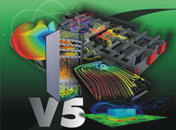 Flomerics V5 Integrates Physical Design in One Environment
A new suite of software products from Flomerics (Southborough, MA; flomerics.com) integrates many contributors to electronics design in a single analysis environment. Flomerics Version5 consists of Flo/PCB for conceptual thermal design of printed circuit boards, FloTHERM for system-level thermal design and optimization of electronics systems, Flo/EMC for electromagnetic compatibility (EMC) simulation, and Flo/STRESS for predicting thermomechanical stresses. The new suite was designed to cut leadtime by addressing all these aspects in a single analysis environment, and eliminating team communications barriers.
The new process typically begins when the systems architect develops the initial concept block diagram in Flomerics’s Flo/PCB. Hardware design engineers can then derive the first physical layout directly from the block diagram. A 3D computational fluid dynamics solver predicts airflow and temperature for both sides of the board in minutes, so cooling management can be considered from the earliest stages. Changes made to the functional block diagram are instantly reflected in the physical layout and thermal representations. This keeps all team members in sync and enables them to contribute to concept development in real time.
As mechanical engineers develop the physical design, they can drag the Flo/PCB model into a system level thermal design developed with Flotherm. Accurate information is transmitted to mechanical engineers and design changes are immediately broadcast and thermal issues can be dealt with before prototypes are available. The same model can also be used to address EMC issues earlier than is typically normal without calling in an EMC specialist.
The analysis environment is supported by smartparts3d.com, an extensive web-based library of ready-to-run models for common parts such as fans, heat sinks, IC packages, and standard enclosures.
TurboGrid Adds Speed to Meshing Tool For Rotating Machinery
ANSYS, Inc. (Canonsburg, PA; ansys.com) has added speed, automation, flexibility, and mesh quality to CFX-TurboGrid 2.2.
CFX-TurboGrid 2.2 creates meshes specifically for computational fluid dynamics (CFD) analysis of bladed rows for a wide range of axial and radial turbomachinery components. Version 2.2 combines both the sector-specific knowledge of CFD simulation for rotating machinery from ANSYS CFX and mesh generation technology from ANSYS ICEM CFD.
CFX-TurboGrid 2.2 automatically generates the meshes by determining appropriate parameter settings based on prescribed heuristics that account for the geometry with little or no user input. Meshes use hexahedral elements only, and important geometric areas such as the tip gap can be included. Both interactive response time and speed of mesh generation has been improved. CFX-TurboGrid 2.2 uses new interactive features to refine the mesh, so that changes to the mesh are displayed interactively. Turnaround time for full 3D mesh generation can take 10 seconds for one million node meshes on a typical modern desktop PC, according to the company.
3G.Design Simulation Suite 2004Plus Increases Functionality
PlassoTech, Inc. (Los Angeles, CA; plassotech.com) has begun shipping 3G.Design Simulation/Optimization Suite 2004Plus, including 3G.author, 3G.central, and 3G.access. The capabilities in the new release include a nonlinear structural analysis module for large deformation and advanced contact simulation, extensive shell element-based functionality, and extended load types.
The 3G.Design Simulation/Optimization Suite 2004Plus offers a new nonlinear structural module enables analysis of large displacement models made with solid and shell elements. The module also supports contact analysis of assemblies subjected to large deformation. A new option enables pin type contact point definitions at various locations on or off the model. Users get the advantage of advanced nonlinear simulation capabilities within the 3G.author environment. Additional new contact capabilities for analysis of assemblies includes shrink-fit with and without sliding conditions.
A new capability allows creation of shell models from various parts and assemblies for structural, dynamic, nonlinear, and thermal analyses. In addition, users are able to open surface-based models from CAD applications, create a shell mesh, and obtain parametric-based simulation results. Postprocessing for shell type models allows viewing top and bottom shell stresses as well as rotational components.
Subscribe to our FREE magazine, FREE email newsletters or both!
Latest News
About the Author
DE’s editors contribute news and new product announcements to Digital Engineering.
Press releases may be sent to them via [email protected].


