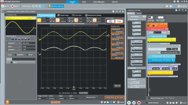
Graphical programming can help engineers implement a more automated testing process. Image courtesy of Keysight Technologies.
Latest News
April 1, 2016
 Graphical programming can help engineers implement a more automated testing process. Image courtesy of Keysight Technologies.
Graphical programming employs images and symbols to allow users to communicate complex systems visually, without coding. It can be used to test design parameters and find changes that will improve the overall design outcome.
To explore this topic, DE spoke to Jeff Phillips, section manager for Software Platform Marketing at National Instruments; Michael Carone, senior product marketing manager for Simulink at MathWorks; and Jeff Smith, software marketing manager at Keysight Technologies. The conversation centered around graphic programming trends for design engineering applications.
DE: How would you describe graphical programming and its utility for automated testing? What are its key advantages and attributes?
Jeff Phillips, National Instruments: A picture is worth a thousand words. At its core, graphical programming is a development paradigm that leverages the human capacity for understanding complex information in the form of a drawing as opposed to words. Graphical programming actually aligns very well with the way engineers visualize systems, in general, and test systems, in particular.
Engineers can focus on the components of a system and their connectivity, and represent that directly in a graphical language, rather than wasting time trying to determine the proper abstractions to use from a more traditional programming language. The artificial complexity of traditional programming often exceeds the inherent complexity of the task to accomplish.
Michael Carone, MathWorks: An advantage of graphical programming is the application of this technique to find design errors earlier in the development processes. Most design errors are introduced in the original specification, but aren’t found until very late during the integration testing phase on actual hardware.
In this environment, engineers are able to analyze their designs in a simulation environment, perform various what-if analyses, run tests in simulation on their desktop computer, identify incomplete or missing specification requirements and determine the overall robustness of the design.
Once the design has been confirmed to work in simulation, you can use code generation tools to automatically generate code from the simulation model. In summary, the benefits include: prototyping via desktop simulation; automatic code generation for embedded deployment; and early test and verification of embedded systems before hardware has been built or code has been written.
DE: So, what exactly is the difference between traditional programming and graphical programming?
Phillips: There are two fundamental differences. Traditional programming is text-based and sequential, while graphical programming is pictorial and parallel. Text-based languages use words, symbols and esoteric syntax to construct programs, while graphical languages use icons, boxes and lines to construct programs. It is much simpler to see the relationships among the components of a program graphically vs. textually. Traditional languages are modeled on the von Neumann computer architecture, which executes sequentially, so using them to create correct parallel programs is notoriously difficult. Graphical languages, on the other hand, are inherently parallel so they are much better suited to program parallel programs on modern multicore processors.
Carone: Traditional programming is text based. You write code — that is your program. With graphical programming, your design is represented by blocks and lines. Blocks typically represent mathematical and logical algorithms; lines represent data. One of the main benefits of graphical programming is that it is easier to understand for the person who wrote the original program, and for their colleagues as well. This is especially true for specialized software, such as embedded control or signal processing systems. In those areas of engineering, the college classes and textbooks use block diagrams to represent algorithms and to explain concepts.
DE: What’s unique about graphical programming that can expedite automated testing for design and testing?
Phillips: Graphical programming can more easily support the testing of multiple devices in parallel, greatly reducing test time and cost for high-volume manufacturing. For complex devices, graphical programming makes it easier to test multiple features at the same time, for example, concurrently testing RF (radio frequency) communication and brightness uniformity of a display.
Jeff Smith, Keysight Technologies: Engineers need the fastest path to their results. Time is limited as it is, so spending half of a day programming instruments or setting up data acquisition software isn’t the best use of time for many design-focused engineers. Heavyweight programming isn’t always needed for design characterization tasks that will change or evolve over the normal course of a new design. As such, some users have gravitated toward graphical programming languages because learning this can be faster than learning a traditional text-based language.
However, as graphical languages have become more flexible to support more uses, they have also become more complex, increasing the learning curve and burden of test design. This has led to a cottage industry of training classes and certifications for graphical languages that don’t necessarily translate to other areas of the industry.
DE: What are some key features and developments to watch for in graphical programming?
Phillips: One of the key recent developments in the market has been the proliferation of multicore processors and FPGAs (field programming gate arrays). These are highly parallel processing elements and ideally programmed by graphical languages. They are also becoming more complex by integrating communications and I/O.
Graphical languages are superbly suited to representing I/O and communications paths as well as precise timing relationships so there will continue to be advances in these dimensions. The capabilities of graphical user interfaces (GUIs) have expanded dramatically in the recent past and it will be natural for graphical languages to exploit more elements of modern GUIs in the service of making domain experts more productive.
Carone: One of the key developments in graphical programming is to incorporate the advantages of traditional textual programming inside of a graphical model. For example, Simulink now enables users to type in the name of a block in order to add it into the model instead of having to find that block within a library browser. Furthermore, in Simulink, algorithms from MATLAB, C or other text-based languages can be added directly into the model.
Web browsers are also inspiring some of the enhancements to the graphical programming environment. These include view marks to save particular views of a model, similar to using bookmarks to easily go back to a website, and tabs to switch back and forth between different levels of hierarchy within the model, similar to tabs used to switch back and forth to different websites.
Smith: In response to the market need for a simpler approach to common problems, Keysight Technologies introduced an automation application last year that greatly reduces the programming burden of users who need simple automation with their test instrumentation.
With the Keysight BenchVue Test Flow application for BenchVue Software, engineers can easily create automated sequences with test and measurement equipment. If you understand the basics of a DMM (digital multimeter) or oscilloscope or other common instrumentation, you can drag controls and measurements from dedicated applications in BenchVue to create your own automated sequence with a combination of different instruments. No longer are engineers tied to downloading the right driver or finding the right command syntax for their instrument. With the BenchVue interface, the most common controls are presented for users independent of model number.
For those engineers who need the power and flexibility of a complete programming environment for full automation, Keysight offers tools that augment the development environment of the user’s choice. One example is Keysight’s Command Expert software that helps bridge the gap from getting the right commands for an instrument to exporting to the development environment of choice. Command Expert walks through the process of finding the right SCPI (standard commands for programmable instruments), helps to fill out the parameters of that command, then arranges the commands into a sequence that can be either used to get the measurement itself or exported to cross discipline programming languages such as MATLAB, C#, Python, LabVIEW and others.
More Info
Subscribe to our FREE magazine, FREE email newsletters or both!
Latest News
About the Author
Jim Romeo is a freelance writer based in Chesapeake, VA. Send e-mail about this article to [email protected].
Follow DE


