Latest News
June 1, 2005
By Anita Bestelmeyer
BD Technologies manufactures and sells a broad range of medical supplies, devices, laboratory equipment, and diagnostic products. Many of our products are disposable plastic devices made from medical-grade plastic resins with some rubber and steel components. Healthcare institutions, life-science researchers, clinical laboratories, and the general public are among our major customers.
At BD, FEA comes into play early in product development. The CAE Analysis services group, where I work, enjoys a wonderful collaborative relationship with BD product engineers. We communicate across geographic boundaries using web-based desktop sharing tools. The web allows us to convey analysis results to the engineers while holding real-time conversations with them about their design concerns.
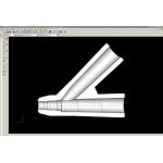 |
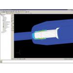
| Cross-section of a solid model after being imported into ABAQUS/CAE for a shelf-life simulation. The component is part of a sealing assembly. To begin a study of the sealing forces, BD analysts determine that the important area of contact is located to the left of the Y-junction. Click on image to enlarge. |
We take our role as partners seriously, so we look for CAE simulation tools we can rely on to optimize part functionality and moldability, improve time to market, lower cost, and prove out new technologies for products. Our CAE Analysis group has been using ABAQUS software for about 20 years. ABAQUS has the ability to simulate complex problems involving multi-body contact, nonlinear plastic and rubber materials, large deflections, and other factors related to the durability and performance of our products.
In the past, we used non-ABAQUS modeling and meshing tools as a front-end to set up for our ABAQUS structural analyses. Now, though, we have switched over to using the latest ABAQUS/CAE interactive interface for preprocessing. Version 6.5 of ABAQUS/CAE introduces many new features that make it easy to set up an analysis. The advantage for us is a streamlined analysis workflow that obtains faster results for BD product engineers.
Shelf Life of a Seal
We use structural analysis to evaluate many different kinds of design and manufacturing problems, such as sealing and activation forces, rotation torque, thermal heating, dimensional tolerances, shelf life, and so on. We often combine shelf-life simulation with other analyses. In a sealing application, for example, the product engineers may also wish to make sure the device will achieve its sealing force requirement over its entire shelf life of perhaps three years.
A typical sealing assembly includes a rubber stopper, plastic barrel, and plunger rod. One objective in our analysis is to evaluate the sealing force at the interfaces between the parts and predict any deformation that might be caused by the force of the compressed stopper during the product shelf life. The first step in setting up an analysis is to import the product geometry into ABAQUS/CAE.
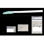
Sample steps in setting up a shelf-life analysis using ABAQUS/CAE
 |
| 2a |
 |
| 2b |
2a (above left) shows the 2D analysis model during definition of material properties.
BD analysts define the area highlighted in green as polypropylene and enter stress-strain and creep behavior characteristics based on test data. 2b (above right) shows the application of boundary conditions to define the behavior of the sealing components during simulation. The color-coded guides are used to make the definition easy to track. 2c (right) shows the meshed model checked for errors. Note the denser mesh created where sealing forces are of greatest interest. Click on images to enlarge.
2c
Most 3D solid models are overly complex for the purpose of FEA, so before defining loads and constraints, we usually simplify geometry. The ABAQUS interface offers two approaches for doing this. The virtual topology tool lets us click on any number of small surfaces and combine them into one larger blended surface. The repair geometry tool deletes irrelevant features from the design and sews up the geometry underneath in a perfectly self-healing way. It doesn’t matter what native package the geometry was created in. Once the boss or fillet is removed, the software is smart enough to repair the remaining geometry.
In this case, after importing the geometry into ABAQUS/CAE, we care most about looking at the surfaces that have to seal (see Figure 1, above). If there are bosses or fillets or ribs on external areas that do not affect the sealing, we can remove them or blend them together. The software allows us to make a judgment about which surfaces are important and to focus on them.
The next step in our analysis is to import material information from our in-house database and match it to each component in the product model. For a shelf-life simulation, we require two pieces of information for each material in the model. We need the stress-strain data, which are originally generated from tensile tests. Our material vendors supply us with engineering stress-strain data, and we convert it to true stress-strain data for ABAQUS.
We also need the creep constants for each material. Creep behavior is determined in a test lab by hanging a weight on a test specimen and observing how it deflects over time. This long-term stress-strain data is then curve fit to determine creep constants using the available creep models within the ABAQUS program.
After we insert the material data into the analysis model, we are ready to define the analysis attributes. Having an interface specifically for ABAQUS is a great advance. Our old method was an elaborate workaround that required us to define loads, constraints, and contacts based on mesh nodes and elements instead of geometry. We then had to run the job through a postprocessor so that it would be in the correct form for the ABAQUS solver.
As a consequence, every time the geometry changed, we had to remesh the model and select our definitions all over again. This added a lot of unnecessary time to every analysis run and introduced the potential for error. Now the process of defining contact, constraints, loads, and boundary conditions is very visual, and attribute definition is based on the geometry of the model.
Meshing also goes more smoothly. We never have to worry about meeting the mesh quality standard for the ABAQUS solver. We can do a mesh check right in the interface. Our old mesher would often let errors go, and then when we went to run the job, ABAQUS would kick it out because it didn’t meet the mesh criteria. We then would have to go back through all those steps: remesh, redefine analysis attributes, postprocess, and submit the job again.
A physical test of a seal can show whether the seal functions or not, but it doesn’t offer a detailed picture of the force along the sealing interface. Simulation can show the product engineer exactly where the seal is occurring. If the force is too localized, the engineer may send us some new geometry to fix the problem. Model definition within ABAQUS/CAE is color coded, so it’s very easy to keep track of contact pairs, boundary conditions, and so on, and to make quick changes to geometry (see Figure 3).
Streamlined Design Collaboration
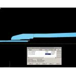
3a (above left) shows the predicted sealing forces for the product immediately after assembly, but before accounting for creep behavior during the product shelf life. 3b (above right) shows the predicted forces, including creep behavior, indicating how the seal will perform as the material relaxes over time. Click on images to enlarge.
; "Image")
Because ABAQUS/CAE is geometry based, it is very friendly to a development environment that encourages collaboration between analysts and product engineers. Early in development, we can easily swap alternative geometries in and out of analysis models, so the engineers can try creative solutions when making decisions. Later on in development, simulation helps us optimize product designs for performance, durability, and manufacturability.
In fact, over the last couple of years, our group has been working closely with product engineering on a method to conduct virtual design-of-experiments. The product engineers vary their design parameters across 16 or so cases, and we run analyses to discern which are the critical design variables that most affect part performance. The engineers then use the information to make a design more robust and cost effective.
With ABAQUS/CAE, our analysis workflows are now so efficient that we can do these multiple case studies in less than half the time they would otherwise take. The capacity we are building for increased analysis throughput will help support a company-wide rollout of Design for Six Sigma in the future.
Anita Bestelmeyer is CAE Analysis Manager at BD Technologies. You can send Anita your comments about this article through e-mail c/o DE‘s Editors.
How BD Uses Simulation
• Optimization of medical devices to meet end-user force and deflection requirements
• Verification of device sealing performance
• Prevention of structural integrity issues through simulation of potential failure modes
• Quick assessment of how material possibilities will affect part performance
• Long-term creep simulation to assess part functionality during entire product shelf life
• Evaluation of tolerance stack-up effects on product assembly and performance
• Virtual design-of-experiments to determine critical part parameters driving robust product performance
• Knowledge of safety factors with respect to target operating space for product
• Reductions in cost and time due to decreased need to create and test physical parts—AB
Collaborating with ABAQUS
The ABAQUS/CAE visualization module is a very slick postprocessor and has many nice features. At BD, we use it exclusively to postprocess our results and share important information via the web with divisional customers located throughout the country. We call the product engineers, open our desktop-sharing tools, and bring up the deformed shape, color contour plots, and x-y plots in the ABAQUS interface. We then all talk about and view the simulation results in real time. Collaboration saves us time by promoting quick and informed decision-making during product development (see Figure 4).
For a sealing application, we would show the product engineers both ends of the shelf-life spectrum so they understand how their as-designed components are predicted to deform immediately after assembly and at the end of the desired shelf life. The results show them exactly where the sealing forces occur in the assembly and when the forces begin to change over time.
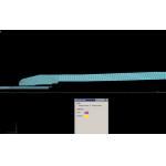
View of a collaboration session between BD analysts and engineers. Using desktop-sharing tools, BD product engineers at any location can interact with the ABAQUS/CAE results interface while having a conversation with BD analysts. If the product engineers decide the seal is too localized to meet the shelf-life requirement, they can send new model geometry for a quick analysis iteration. Click on image to enlarge.
Simulation does not completely replace physical testing but promotes fewer and smarter physical tests within the product development cycle. Using analysis, we can predict whether the part will seal at the end of the product shelf life, whereas an elevated aging test could take 10 weeks or more to discover unexpected leakage.
If analysis predicts sealing leakage, we can iterate until the design achieves the desired sealing force at the end of the shelf-life period. We can also use an x-y plot of the analytical results to predict when the majority of decay will occur in the sealing force. This allows us to pull some parts out of an elevated aging test and confirm the desired sealing force in a shorter period.
Some materials have long-term stress-strain characteristics at room temperature and at an elevated temperature. We are able to simulate shelf life for the product at both temperatures. Simulation at room temperature is extremely useful since it can’t reasonably be done using a physical test. Also, it can give the engineer confidence that the new design will perform correctly throughout the expected shelf-life period.—AB
ABAQUS/CAE
ABAQUS, Inc.
Providence, RI
Subscribe to our FREE magazine, FREE email newsletters or both!
Latest News
About the Author
DE’s editors contribute news and new product announcements to Digital Engineering.
Press releases may be sent to them via [email protected].