Portable CMMs Save Time
Discover how rapid shop floor inspection makes quick work of quality.


Latest News
August 1, 2010
By Ron Branch
For the machine shop that supplies the aerospace industry, PCMM (portable coordinate measurement machine) and MBD (model-based definition) are everyday terms that are integral parts of its daily inspection routines. In the effort to drive quality and control processes, aerospace original equipment manufacturers (OEMs) have altered the inspection methodology and the tools of their entire supply chain. Many of these suppliers are small or mid-sized machine shops that have invested in inspection hardware, software and processes to satisfy strict quality standards. With the success of these supply chain efforts, PCMMs and the MBD Inspection technology are expected to spread to all industrial segments.
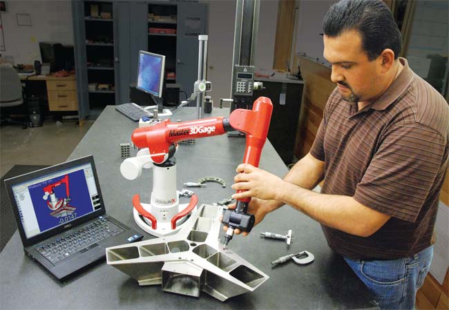 Portable coordinate measurement machines can be temporarily mounted in many areas of the shop, so they can be moved where they’re needed. |
Now, it would appear that these new inspection tools and processes would place a big burden on the machine shop while benefitting only the aerospace manufacturer. It is true that this approach to quality control and inspection does demand more than what the usual assortment of hand tools and gages can deliver. It places much more emphasis on CMM-based inspections, which could mean a big investment in quality control. However, the new quality practices actually benefit the machine shop, fabricator or toolmaker—and it costs a lot less then they might expect.
By deploying PCMMs to the shop floor, these small businesses are realizing great gains without staffing up in the quality control department. These companies are performing thorough and accurate measurements much quicker than previously possible. They have adopted a convenient and efficient measurement process that covers everything from incoming inspection through final part inspection. They have also gained greater control over their processes.
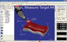 The first step of the process is to align the physical part with the digital CAD model. | 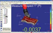 Measurements can be taken by touching the probe to the part, or by dragging the probe across the part. | 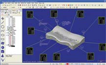 The inspection results can be output in tabular format with reference images. |
So, how do these small shops respond to the demands of aerospace manufacturers and realize all of these advantages? They have adopted a rapid shop floor inspection approach: taking 3D measurements on the floor at the source for immediate feedback and reporting against the engineering quality specifications.
This approach is a growing trend outside of the aerospace industry, and a strategy that many non-aerospace machining and fabrication shops are using today.
Rapid Shop Floor Inspection Tools
There are three items needed to implement rapid shop floor inspection:
- hardware,
- software and
- engineering data
PCMMs, FYI Articulated arms have joints that provide six or seven rotary axes versus the three linear axes of motion commonly used on CMMs. Spanning 4 to 12 ft., these arms allow an operator to position the touch probe in any orientation to capture most, if not all, measurements in a single set-up. Like CMMs, PCMMs can also be outfitted with laser scanners to capture dense point clouds of measurement data. Articulated arms have 6 DOF and positive contact probing that allows for real-time inspection without triggering points. With an articulated arm, the probe approaches the part at any angle without slowing down as it nears the surface. This eliminates probe angle calibration and custom holding fixtures. For large items and structures, PCMMs take on other forms. Using lasers and infrared light, long-range PCMMs can capture measurements to distances of several hundred feet. In industrial applications, laser trackers are the most common form of long-range PCMMs. |
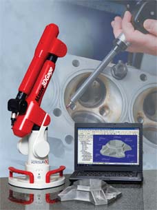
To conduct inspections on the shop floor, a PCMM is needed. Although there are several options, a common PCMM choice for a small machine shop is an articulated arm with a positive contact probe.
Temporarily mounted on any rigid surface, these lightweight devices are easily transported anywhere in the shop. Arms have joints that let the machinist extend and rotate the measurement probe into every channel, bore or pocket. With a reach of 2 to 12 ft., the arms do not have physical size limits common with stationary CMMs. These features make them versatile inspection tools.
The second component of a rapid shop floor inspection system is the software that receives all of the information from the arm. In the most basic mode, the software will log and report measurements taken with the arm. However, the big gains in time and efficiency happen when the software’s full functionality is leveraged. For example, the software will create prompted inspection plans as datums and features are selected while in teach mode. It will also provide real-time inspection data with visual, on-screen references. To really expedite the inspection process, it can import a CAD reference model for direct comparison of the manufactured part to its design intent.
Because the arm will be used in a variety of applications, the software will allow the user several modes of operation:
- Direct measurements for on-the-fly spot checking as an alternative to a hand tool.
- Measurement to drawings in accordance with datums, dimensions and geometric dimensioning and tolerancing (GD&T) callouts.
- Direct comparison to a CAD model that contains the dimensional requirements.
The final piece of the rapid shop floor inspection solution is the quality specification and inspection plan. As just stated, the inspection work can be performed by referencing a part’s engineering drawings. This approach works fine, but the inspection process becomes much quicker when that data is assigned to a digital reference within the PCMM’s software. Start by importing the 3D CAD model, and then assign the quality specifications from the drawings to the digital model. This allows the software to prompt where measurements are to be taken, and immediately report a pass/fail condition.
For the fortunate shops whose clients have adopted MBD, the process becomes even faster. Because the model contains all the quality specifications, it is simply imported—and a few moments later, inspections can be performed. This eliminates all the manual effort to interpret drawings, document measurements and report against the prints.
With these three components—PCMM, software and quality specifications—machine shops have a portable inspection tool that is the equivalent of a cart full of hand tools and gauges, and a roll of engineering drawings. Everything that is needed to determine go/no go is bundled in a rapid shop floor inspection tool that travels to the work piece.
The Process
The PCMM goes to the source of the inspection, which can be on the loading dock, manufacturing floor, machine shop or tool room. All that is needed is a little space and a stable work surface to mount the arm and place the part.
With battery operations and optional wireless communications, truly portable systems do not even require a wall outlet or a cabled connection. After a calibration routine, the system is ready for operation.
In three steps—align, inspect and report—the inspection process is complete.
Defining Model Based Definition In the realm of inspection-related activities, MBDs supply all of the dimensional and tolerance information. There are no drawings. The CAD model contains all of the specifications, including the geometric dimensioning and tolerancing (GD&T) callouts. The dimensional specifications may be either annotations within the model file or digital specifications linked to a feature. With the latter approach, inspections are completed simply by referencing the CAD model and picking the appropriate points on the object. This eliminates all manual documentation and data entry and expedites the inspection process. An advanced concept linked to MBD is minimum dimensioning. With this approach, a global profile tolerance is applied to the CAD model and only those features that are critical to function are explicitly defined through GD&T callouts. |
Step 1, align: Start by placing the part within range of the arm. No fixturing is needed as long as the part does not move while
measurements are taken. Next, probe the reference surfaces (e.g., datums) that align the physical part to the
digital CAD model. Now, the part is ready for inspection.
Step 2, inspect: Take the desired measurements by touching the probe to the part, and click the record button. Just touch and go on to the next measurement. Alternatively, drag the probe along a surface to pick up a continuous stream of measurements. With each measurement that is made, the system gives immediate, on-screen feedback. The dimensions and deviations are annotated in green when within the specified tolerance band, and in red when the dimension fails.
Step 3, report: When the inspection is complete, output the results in an inspection report that presents the information in the traditional tabular format augmented with any desired reference images.
When describing his rapid shop floor inspection process, one tooling inspector stated, “The beauty is that we simply align the model and start checking it. We get immediate reporting and feedback.”
This is in stark contrast to the time, effort and talents needed when using traditional measurement tools.
The Advantages
As can be seen through the description of rapid shop floor inspection, it provides the capabilities of a stationary, programmable CMM while offering the convenience and flexibility of hand tools and hard gauges.
Measurement results are produced quickly with little effort, which is what the small- to mid-sized shop needs. But how quick is it? One aerospace supplier stated that when inspecting with a measurement arm against a CAD reference model, the process took just 10 minutes. Without a PCMM and the CAD reference model, the same part took 12 hours to inspect. That company also offered an example comparing an arm to a CMM. Inspecting to prints, the arm was 75% faster than a manually operated CMM.
The bottom line is that rapid shop floor inspection makes it quick, easy and painless to measure parts and assemblies often and thoroughly. This lessens the likelihood of running “at-risk;” minimizes scrap and production delays; and maximizes product quality.
More Info:
V&M Precision Machining and Grinding
6 Ways to use Rapid Shop Floor Inspections
1. Inspecting incoming parts. When the truck backs up to the dock, roll the arm over to meet the incoming parts. Instead of sending them to wait in the queue at the CMM, they can be thoroughly inspected as they arrive. With on-screen feedback, each is passed (or failed) before being carted into the plant. Also, the system will record all results for traceability and trend analysis. 2. Checking parts in/out of the process. Before starting a new manufacturing operation or sending parts on to the next process, use the arm to confirm the quality of the part. As noted earlier, in/out inspection can even be performed while the work piece is fixtured in the CNC mill, router or lathe. 3. Verify tooling. The quality of jigs, fixtures and dies is important to the quality of the parts that they make or align. Use the arm to inspect them when put into service. For long-running tools, use it for routine measurements to check for wear, damage or distortion. 4. Align parts and tools during the build. Rapid shop floor inspection is ideal for fine-tuning part alignments before assembling components. For example, use the arm to check the positioning of pieces held by a welding fixture. Adjust the parts as recommended by the inspection software before hitting them with the first tack weld. 5. Monitor process controls. In the day-to-day operations of most machine shops, lot sizes are too small for statistical process control (SPC), production part approval process (PPAPs) and process capability indices (CpKs). But this does not mean that machine shops do not have to worry about process control. Over time, process parameters shift and tools wear, so the machine shop needs to routinely check output quality to catch variance before it becomes a problem. For process control, rapid shop floor inspection helps in two ways. First, it can assist in identifying the process variables that must be controlled to produce good parts. Second, it can be used for spot-checking to confirm that those parameters are stable. 6. Problem detection and diagnosis. Rather than inspecting parts or processes to a pre-defined plan, the arm can be used to query the part to determine where the problem lies and what its root cause is. The arm offers the flexibility to conduct “what-if” diagnosis to understand the cause and effect. |
Ron Branch is a manufacturing engineer for V&M Precision Machining and Grinding. Branch has 20 years experience as a machinist and more than 15 years of CNC programming. Contact him at [email protected].
Subscribe to our FREE magazine, FREE email newsletters or both!
Latest News
About the Author
DE’s editors contribute news and new product announcements to Digital Engineering.
Press releases may be sent to them via [email protected].