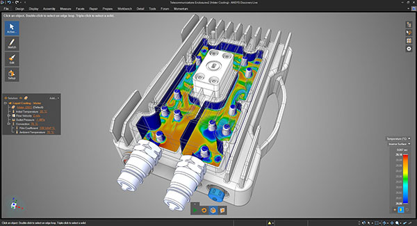
With quick real-time analysis, Ansys Discovery targets designers with limited exposure to simulation. Image courtesy of Ansys.


Latest News
January 26, 2024
In an era when computing cost a premium, simplifying a simulation model was critical for preprocessing. Your workstation had only a finite number of CPU cores and graphics processing unit-based computing was still in its infancy, so if you put all your cores to work on your simulation, your computer was essentially dead for the duration of the job.
To avoid maxing out or to reduce the wait time, simulation software users learned to employ various methods to reduce the computation burden. Defeaturing and physics simplification were the two common strategies. But in the current era of GPU-accelerated workstations and on-demand cloud computing, are these methods still relevant? And if they are, what are the pros and cons? To find answers, we spoke to two simulation experts.
Know Your Pain Threshold
Tony Abbey, a frequent contributor to DE 24/7 and a trainer at NAFEMS, recalls, “Twenty years ago, people had to be really miserly with the degrees of freedom, or the scope of the analysis. But today, with GPU computing, it enables us to do a lot more. But just as the kind of simulation we can run casually has increased, so has the complexity of simulation jobs.” (For info on Abbey’s courses, click here.)
Krystian Link, solution engineer, Rand Simulation, agrees that today’s workstation can easily process what used to be impractical, but adds, “Sure, you can throw more mesh elements at a problem, but is that really a prudent use of your time and hardware?”
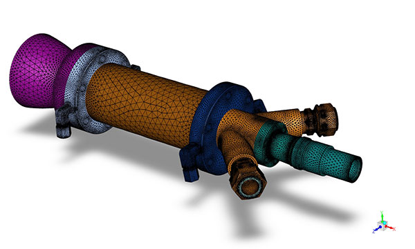
The same simulation model prepared with coarse mesh to reduce processing time.
Abbey recommends FEA users do some benchmark testing of their own hardware—whether it’s a workstation, a laptop or a hybrid mix of cloud and local hardware—to identify their own limits. Depending on your primary job function, there’s usually what you consider a reasonable processing time. Benchmarking helps you identify the size and scope of simulation (usually defined by the number of elements or degrees of freedom involved) your hardware can comfortably process within what you consider to be an acceptable timeframe.
“If you’re a designer, maybe you want to get that design’s stress checked in two or three minutes. If you’re an analyst like me, maybe you’re prepared to go and have a cup of coffee and come back to get your results in 10 to 15 minutes. For important jobs, maybe even a whole day,” he says.
A Critical Question Before You Defeature
Defeaturing, or simplifying the geometry targeted for analysis, is one of the most common methods to cut down processing time. Usually, you eliminate rounded edges, bolts, screws and holes, leaving the geometry mostly as primitive blocks. This reduces meshing and processing time. But using it as a universal approach might not be wise, Link warns.
“Think of defeaturing like throwing a stone into a pond with a paper boat in it. The boat represents the area of your model where you are collecting your results,” he proposes. “The question is, will the defeaturing you did affect the area you care about most? Will that boat feel the ripples?”
If a hole or a rounded edge lies outside the region where you are collecting data within the simulation and doesn’t play a role in the overall simulation, it’s clearly safe to defeature them. On the other hand, if they’re in the stress- or temperature-impacted region, then defeaturing them might affect the accuracy of the results.
Link also points out that defeaturing considerations for computational fluid analysis (CFD) expands on techniques that are used in structural analysis. For instance, in CFD, liquid conveying systems are designed with smooth curves to avoid sudden pressure buildups, and certain holes could play a big role in the overall system performance, such as relieving pressure, diverting flow and mixing fluids.
“If you put mesh elements around sharp points, those elements can become so skewed that the math running within them may no longer represent the system accurately. In fact, these sharp edges could potentially cause the simulation to diverge and the software to crash,” Link warns.
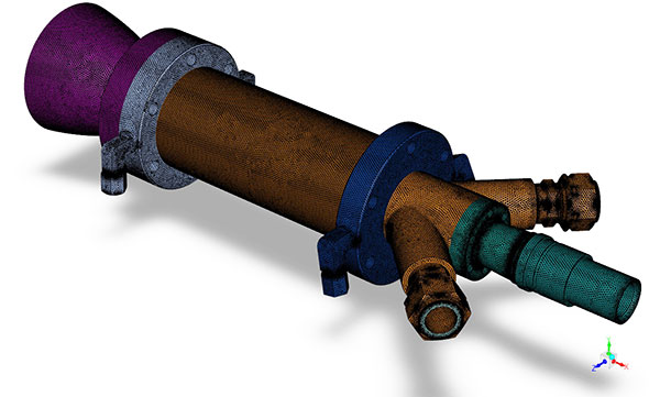
“It’s a good idea to do some initial mesh sensitivity studies,” he suggests. “Start with a really coarse mesh, look at the results, then start refining the mesh to see how the results change. That gives you a good idea of what happens when you turn these dials.”
Abbey, too, is skeptical of the push-button defeaturing approach, which automatically selects all the holes and rounded edges in the design and removes them. He says, “It would be fine to defeature in the external corners where the stress gradients are low.”
Abbey believes that in the future, artificial intelligence-powered simulation software could become intelligent enough to make such judgements based on the boundary conditions. “I don’t think we’re there yet; we’re still in transition,” he adds.
Know Before You Slice
Another common approach is extracting a midplane surface, or a 2D cross-section of the target geometry, then using it as a substitute for 3D analysis. Link said this approach is useful if you suspect your hardware might run out of horsepower if you run 3D analysis of the whole system.
Link gives an example of simulating a steam-generation power plant. “That would take lots of computational resources, and maybe you are in a situation where you are willing to make that sacrifice of going to 2D instead of 3D simulation,” Link says. In certain simplified flow situations, the 2D approach might be useful, he adds.
“However, with today’s powerful workstations, for most cases, the data you can collect makes it worth the time penalty for running a full 3D simulation compared to 2D simulations,” Link notes. “I haven’t encountered too many situations where choosing a 2D simulation was the preferred method over 3D.”
“You have to look at the symmetry in the model,” advises Abbey. “Does it have symmetry in loads, in materials, in geometry and so on? If that’s the case, the stress response will obviously be symmetric, so why not slice the model?”
Abbey warns that this approach is acceptable only in about 10% to 15% of the cases he has encountered. And historically, experts like him are the ones who make the judgment. “If it walks like a beam, talks like a beam, then I know I can model it as a beam element. And if it walks like a shell, talks like a shell …,” he quips. “But if you come from using CAD-embedded 3D simulation tools, it’s painful to do that.”
To reduce the design first to simple 2D elements before approaching it in its full complexity in 3D is generally how an expert like Abbey thinks. But for a designer who learned to simulate using 3D CAD models as the starting point, reverting to 2D midplane thinking is not easy, Abbey warns.
Many mainstream CAD programs like Autodesk Fusion 360 and SOLIDWORKS offer CAD-embedded simulation features aimed at the designers. They’re meant as concept-phase design evaluation tools. As such, they rely more on default settings and automation to avoid overwhelming the user with too many choices. Experts like Abbey, on the other hand, tend to rely on more sophisticated tools with a wider range of input options.
One Physics at a Time
Another way to speed up simulation is to reduce a multiphysics event into a single physics event. In real life, all physical events involve various types of physics, but in simulation, the critical question is, which physics is critical to the answer you seek? For example, if you’re mainly interested in peak temperatures inside a chamber, can you ignore the structural impact?
Link advises against making such decisions on your own. “The danger from making a decision like that in a vacuum is that you could miss something known to other subject-matter experts who possess tribal knowledge of the product’s past performance or even different design perspectives. Or you might not be aware of the impact on the broader system,” he says.
“A good approach is to think about the physics involved and the stress propagation before you run a full-bodied nonlinear analysis of the system,” says Abbey. “To get to the physics that matters, you have to chip away at the problem. Maybe first, you start with a linear analysis, where you choose to ignore the large deflections and contacts. But then, when you get a feel for what’s happening, you introduce large deflections and contacts, add material nonlinearity and so on.”
To simplify or not to simplify, is a question of balance. A full-fledged 3D simulation with fine mesh or high-resolution meshes takes more time, but the results are generally considered more reliable. Using a simplified model for simulation saves time, but the simplification strategies might affect the accuracy of the results. Those in the concept design phase tend to employ a wide range of simplification strategies. But as the design gets close to manufacturing or the point of no return, expert-guided detailed simulation becomes critical as the penalty for design flaws and revisions is much higher.
“In the concept phase, you’re trying to understand design A’s performance in relation to design B, C, and D,” Link says. “You’re not aiming for zero to five percent accuracy. If you use tools like Ansys Discovery, you’re able to iterate through your designs quickly, narrow down the most optimal design candidates for further development, and minimize engineering resource spend within a given project or program.”
Ansys released Ansys Discovery in 2017 as “real-time simulation for rapid product exploration.” It targets designers with its quick response, made possible by GPU acceleration and cloud-hosted setup.
More Ansys Coverage
More Autodesk Coverage
More NAFEMS Coverage
Subscribe to our FREE magazine, FREE email newsletters or both!
Latest News
About the Author
Kenneth Wong is Digital Engineering’s resident blogger and senior editor. Email him at [email protected] or share your thoughts on this article at digitaleng.news/facebook.
Follow DE

