Embedding the Flow
From the purview of experts to an easy-to-use solution that offers benefits for every stage of the product development cycle.


Latest News
July 31, 2007
By Chris Watson
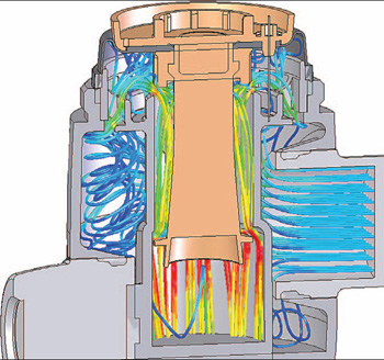 Johnson Design used Flomerics software to determine velocity trajectories on this crosssection of a new valve design. |
Computational fluid dynamics (CFD) has traditionally been a research tool used by analytical specialists at the latter stages of the development process. It can provide fluid velocities; pressure and temperature predictions throughout an area defined by the user; and can model complex geometries as well as boundary conditions. In fact, it provides more complete information than physical testing.
Among other reasons, CFD became popular with analysts because they could increase the value of their analyses by easily changing the geometry of the system or the boundary conditions (e.g., inlet velocity, flow rate, rotational speed, etc.) and view the effect on fluid flow. And the graphic results gave designers more understanding than prototype tests, often enabling rapid design improvements.
But CFD’s use was not widespread due largely to the limitations of price; the need to translate CAD geometry to analysis formats; and required expertise in various meshing options, physical models, and boundary conditions. Yet as CFD became more important to the design of a wide range of different products and processes, its limitations have been addressed by a new generation of software that is fully embedded in the MCAD environment.
Recent commercial CFD codes have interfaces that look and operate like MCAD software and CFD solvers that interact directly with native solid model data. This means the user does not have to translate data, so the solid model maintains intelligence such as assembly hierarchy, constraints, and features. Analysis of the geometry and generation of the computational grid takes place in the background while the user only needs to interact with the familiar MCAD interface. The result is an easy-to-use tool for design engineers and other team members at every stage of the product development cycle. In fact, engineers are now using CFD to test concepts during the pre-development phase to determine design viability and optimize the performance of the near-final design.
Oce Printing Systems
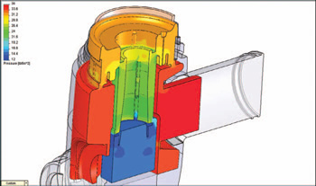 Here is a pressure distribution illustration of the Johnson Design valve cross-section through its center. It helped the company determine the restriction on the rolling diaphragm in the resulting assembly. |
One example of this is Oce Printing Systems in Poing, Germany. As an innovator of production printing systems, the company uses CFD software before it begins developing specific products to investigate theoretical concepts that offer the potential for performance improvements.
“I am the theorist in the company and am more involved in research than in development,” says Rainer Hoffmann, director of Development, Technology and Key Components for Oce. He explains the critical role of research at the company: “I do not just simulate air flows but also other subprocesses in the printing process such as finite elements, electrostatics or magnetostatics, and also the toner movement within the printer.”
Hoffman calculates the ventilation and the suction of the charging units within the printer. The photoconductor of the printer must be loaded with high-voltage wires, which must be evenly ventilated over their entire length to function properly, and the geometry of the long and thin wires presents calculation challenges. Any deviations become visible in the form of an annoying stripe on the printed page.
In this application, as with many others, simply performing simulation does not improve the design. The results of the simulation must be interpreted correctly and considerable experience is necessary to make the right decisions. And who is better qualified than the design engineers to perform simulations on their own designs? MCAD-embedded CFD empowers them to do that.
“We perform some tests to validate our CFD model,” says Hoffmann, “but after validation the number of tests needed is drastically reduced. We have now progressed to the point that we only carry out 10 percent of the tests which were previously necessary. Simulation thus provides enormous cost saving by reducing expensive test setups.”
Grohe AG
 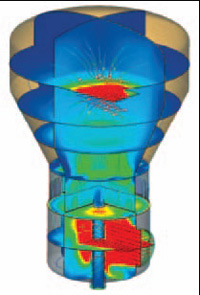 Engineers at a German maker of continuous fluid bed and sprouted bed systems for the pharmaceuticals, food, and chemicals industries used Flomerics CFD to get important visual feedback about the behavior of particles inside a recently built machine. Image courtesy of Glatt Ingenieurtechnik GmbH. |
Grohe, a leading manufacturer of kitchen and bathroom faucets and fittings based in Hemer, Germany, also uses CFD from the earliest stage of the development cycle. For example, Grohe recently used CFD to design a faucet with an integrated thermostat that allows the water temperature to be pre-selected and then automatically maintains it at any water volume. At the heart of this new generation of thermostats is the thermostat cartouche, a completely new development in which the entire flow was determined in advance with CFD.
“Frequently we just need to take just a few measurements to validate the flow analysis,” says Kai Huck, a flow analysis expert for Grohe. “This approach offers very great assistance, especially in the early development phase with respect to optimizing the control parameters. The new compact cartouche reacts twice as quickly to fluctuations in pressure compared to its predecessor, for example.”
The new faucet also has a “cool touch” feature, which guarantees that the external temperature at each point of the thermostat is a maximum of one degree Centigrade above the selected temperature of the water flowing out. This is achieved by using the cold water inlet as a cooling jacket within the thermostat fitting.
“To this end we simulated the surface temperature of a fitting in order to recognize at which points temperature fields arise and in which areas the design of ducts would have to be changed in order to reach the respective temperature target,” Huck explains. “One of the most important parameters for us is always the volume flow rate, which can be measured easily. When we build and test prototypes, the difference between our measurements and the CFD predictions is almost always below 3 percent. It is very easy to learn and use CFD software that is embedded within the MCAD system. The graphical output provides considerable insights into the performance of the proposed design. Technical and non-technical people can understand them and jointly discuss the advantages and disadvantages of new product concepts.”
Boll & Kirch Filterbau
Another German company, Boll & Kirch Filterbau GmbH, based in Kerpen, manufactures filters and uses CFD to simulate pressure losses so small that they would be very difficult to measure with a prototype.
“There is an American standard, for instance, that says an oil filter in a clean state may generate a pressure loss no greater than 0.35 bar,” says Karsten Cartarius, Research and Development team manager for Boll & Kirch. “In the gas sector maximum pressure loss may be as low as 0.05 bar, an extremely low number. These values have been reduced considerably in recent years because smaller pumps are being used on many types of equipment to save energy. We need to be able to prove that the pressure drop in a filter really is 0.05 bar. It is not practical to reliably measure pressure drops this low, but we can use CFD to simulate the pressure drop with astonishing speed and accuracy. The simulations can be performed at a very early stage in the design process to ensure that the proposed design is capable of meeting the standard.”
Johnson Design
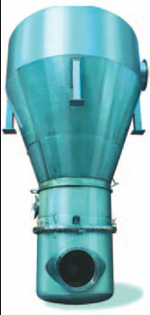
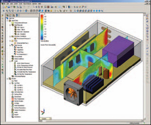 Oce Printing recently simulated the air flow through a virtual model of a new machine to determine proper ventilation and suction properties of the printer’s charging units. |
A unique feature in Carlsbad, CA-based Johnson Design’s Denali Flushometer flush valve is that it delivers a fixed volume of water independent of the position of the restriction on the rolling diaphragm that is randomly installed at various positions during the valve’s assembly process. Rolling diaphragms offer the advantage of exposing only a very small area of unsupported diaphragm to pressure differentials, resulting in much lower forces compared to large-diameter flat diaphragms.
“But it’s usually not possible to determine in advance where the restriction on the rolling diaphragm will end after the valve is assembled,” says Johnson Design Engineering Manager Dustin Borg. “As a result, a weakness of earlier diaphragm valve designs is that one valve of the same model may deliver 1.5 gallons while another will deliver 1.7 gallons. We decided to overcome this problem in designing the Denali Flushometer by evening out the pressure that the valve is exposed to around its entire circumference.”
Borg used CFD to evaluate the performance of the valve as the restriction was rotated 360 degrees to ensure that it delivered the right amount of water in each position. “This would have been a difficult task using physical prototyping because it would have been necessary to repeatedly assemble and disassemble the valve, each time slightly changing the position of the rolling diaphragm,” Borg says. “With CFD we measured the flow rate and pressure at the inlet and outlet of a similar existing valve and used those as boundary conditions. The analysis results showed flow rate and pressure at every section of the valve. The ability to visualize the flow within the valve made it easy to see what was causing pressure variations.… When we built and tested a prototype valve it worked exactly as we expected.”
These examples demonstrate how CFD has become embedded in the design process in many companies, enabling engineers to use simulation to their advantage throughout the product design process. The key to these improvements is the availability of CFD software that provides results directly from the native MCAD data.
According to the most recent Flomerics survey (Oct. 2006), this trend can be expected to continue. When users of mechanical CAD software were asked how important MCAD integration is for typical CFD users, 52 percent said it is “very important today” and an overwhelming 74 percent said it will be “very important in the future.” And most respondents to the survey described CFD integration with MCAD as a “fully-embedded solution in a single environment. The CFD user interface looks and operates like the MCAD software and the CFD solver interacts directly with the ‘native’ MCAD solid model data.”
If the numbers mean anything, they clearly show the trend of using CFD at every stage of development is likely to increase.
Chris Watson is responsible for technical leadership of Flomerics’ EFD product line in North America. He has more than 12 years of experience in the CFD software market. Chris received his B.S. in aerospace engineering from the University of Texas at Austin, and his M.S. in mechanical engineering from Texas A&M. You can send an e-mail about this article to DE-Editorsmailto:[email protected].
Boll & Kirch Filterbau GmbH
Kerpen, Germany
bollfilter.de
Grohe AG
Hemer, Germany
grohe.de
Johnson Design
Carlsbad, CA
johnsondes.com
Oce Printing Systems
Poing, Germany
oce.de
For information about Flomerics’ line of MCAD-embedded CFD software products (EFD.Lab, EFD.Pro, and EFD.V5), visit www.flomerics.com/products/efd/index.php.
Subscribe to our FREE magazine, FREE email newsletters or both!
Latest News
About the Author
DE’s editors contribute news and new product announcements to Digital Engineering.
Press releases may be sent to them via [email protected].


