3D Printing Helps Launch Satellite Mission

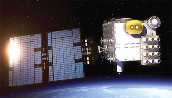
NASA’s JPL is developing the antenna arrays to place on FORMOSAT-7 COSMIC-2 satellites. The mission will collect atmospheric data.
Latest News
February 1, 2015
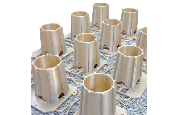
 RedEye used Fused Deposition Modeling and the ULTEM 9085 thermoplastic to create an array that matched NASA’s specifications.
For the aerospace industry, additive manufacturing holds the promise of helping companies reduce cost, weight and complexity for a variety of applications. NASA’s Jet Propulsion Laboratory (JPL) recently collaborated with 3D printing services company RedEye to do exactly that as part of the upcoming FORMOSAT-7/COSMIC-2 satellite launch.
In 2006, a consortium of U.S. research universities and the Meteorological Society of the Republic of China (Taiwan) collaborated on the original Constellation Observing System for Meteorology, Ionosphere and Climate (COSMIC) project, using satellites to collect temperature, moisture and pressure data. A follow up project, the FORMOSAT-7 COSMIC-2 satellite mission, will gather even more weather-realted data. That mission will launch six satellites into low-inclination orbits in 2016, along with another six satellites in high-inclination orbits in 2018. The atmospheric data provided by the satellites will support research in hurricane analysis and prediction, climate processes and other areas.
The Global Navigation Satellite System (GNSS) radio-occultation (RO) payload is being developed by NASA JPL and will be capable of tracking up to 12,000 high-quality profiles per day once both constellations are fully deployed. NASA began its development work in 2011, and additive manufacturing quickly entered the mix.
Control Cost, Increase Speed
Key components of the satellite are actively steered, multi-beam, high-gain phased antenna arrays. COSMIC-2 would use 30 of these traditionally expensive custom arrays, and NASA JPL wanted to find a way to minimize manufacturing costs and assembly time. NASA approached Minneapolis-based RedEye, a Stratasys subsidiary that provides rapid prototyping and additive manufacturing services, to work on the project.
The antenna array supports are usually machined from a composite material called astroquartz, but the COSMIC-2 design would be expensive to produce that way. “Machining those parts was time consuming and costly, and that raised concerns about validating and testing the design,” says Joel Smith, strategic account manager for Aerospace and Defense at RedEye.
“We’re seeing a move in aerospace from traditional manufacturing to additive manufacturing, where it makes sense,” Smith says. “Different companies are using FDM (Fused Deposition Modeling) to make brackets and retainers that are not load bearing. They can take out weight and reduce assembly steps by producing single-unit parts.”
 NASA’s JPL is developing the antenna arrays to place on FORMOSAT-7 COSMIC-2 satellites. The mission will collect atmospheric data.
Using Stratasys FDM equipment, RedEye could produce the structures as a single unit out of ULTEM 9085 thermoplastic. By doing so, NASA’s JPL could quickly create prototypes for testing at a lower cost, and reduce the overall cost and time required to manufacture and assemble the final products.
“The array originally would have been produced in separate parts, and then assembled,” says Trevor Stolhanske, senior application engineer at RedEye. “They wanted to produce the arrays as one unit. They had a rough CAD model, and we worked with them to ensure the specifications would work well with the FDM process.”
“We could also provide flexibility for design changes,” Smith adds. “With additive manufacturing, you can reduce the cost of producing prototypes and end-use items.”
Most 3D-printed parts in the space program have not been for external use on a spacecraft. To create the antenna array supports, NASA and RedEye would have to test and validate the material and the parts to ensure their performance in that environment.
Thermoplastics in Space
When NASA JPL approached RedEye, they had already identified ULTEM 9085 for the application. The material is a thermoplastic that is as strong as aluminum, but much lighter. More importantly, it had already been vetted and approved for aerospace applications.
“It’s a flight-certified material, and one of the more robust materials for additive manufacturing,” Smith says. “It was also a good fit for radio and antenna applications.”
The material had never been used on the exterior of a spacecraft, so the parts had to be tested for antenna beam pattern, efficiency and impedance match, as well as for NASA class B/B1 flight hardware requirements. Those tests included susceptibility to UV radiation, atomic oxygen, outgassing, thermal properties (including compatibility with aluminum panels), vibration/acoustic loads and compatibility with the paint and primer used on the structure.
A high emissivity protective paint was used on the plastic structure to reflect solar radiation and optimize thermal control of the antenna operating conditions.
Collaborative Design Process
The JPL began with a CAD model based on the original machined antenna array design, which was then altered for the FDM process. NASA and RedEye worked primarily in SolidWorks, Magic and Stratasys’ Insight software.
One critical change was the inclusion of 45°, self-support overhead angles in the design to avoid using breakaway support material. That reduced machine run time, increased the printing speed, and minimized part breakage during support removal.
“By eliminating the support material, that creates less havoc when you are removing the support,” Stolhanske says. “You don’t have to remove material from complex areas, and the run time is drastically reduced. The head on the FDM machine does not have to toggle back and forth, layer over layer. You have a twofold savings of run time and support removal, along with minimizing potential damage.”
RedEye and the NASA JPL conducted numerous conference calls and onsite meetings throughout the project to collaborate on the final design. NASA conducted testing of each prototype throughout the process, and would come back to RedEye with any design adjustments.
“With every iteration, there was a design review and modifications made to the drawing and the printed version,” Smith says. “Each part we delivered was a complete component, so they were able to do mock-up assemblies for form, fit and function tests, as well as more detailed changes. They had an end-use part throughout the prototyping phase.”
Between March 2012 and April 2013, RedEye produced 30 of the structures for testing. The JPL and RedEye engineering teams collaborated to process STL files and ensure the parts met exact tolerances. RedEye deburred parts, stamped each with an ID number, and provided a material test coupon, as well as reaming holes for fasteners that would attach to the aluminum panels and small channels in the cones for wiring.
According to Stolhanske, a key challenge was ensuring the wiring holes met the exact tolerances. “The holes had to be a specific dimension that was not too big or too small, and we had to ream precise holes for them,” he says. “It was a challenge because they had to be within a certain spec on their drawings in order to work.”
Each of the antenna arrays requires roughly 55 to 60 hours to manufacture using FDM. RedEye was able to deliver the completed antennas for final testing and integration, and has been added to the JPL Approved Supplier List.
In addition to reducing weight, saving time and reducing costs, NASA was also able to validate the FDM process and materials for use on future projects.
“The aerospace and defense markets are really entrenched in traditional manufacturing, so it takes some understanding and education to make the move to something like FDM,” Smith says. “We were able to provide support for NASA so they could move from concept to finished part, and be able to make design changes without all the cost and time penalties of traditional manufacturing.”
More Info
Subscribe to our FREE magazine, FREE email newsletters or both!
Latest News
About the Author
Brian Albright is the editorial director of Digital Engineering. Contact him at [email protected].
Follow DE


