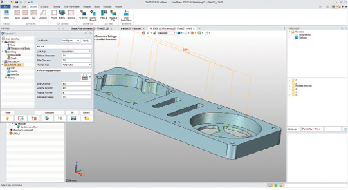
ZW3D provides a well-organized user interface that makes it relatively easy to model parts and assemblies. Image courtesy of David Cohn via ZWSoft.


Latest News
February 1, 2019
The Chinese company ZWSoft’s ZW3D is billed as an all-in-one affordable CAD/CAM program. Although the company and its software may not be as well known in North America, that is certainly not the case elsewhere, particularly in China, where programs like SolidWorks, Solid Edge, Inventor and Creo compete with local brands like ZW3D.
ZWSoft released its AutoCAD-compatible software, ZWCAD, in 2002. In 2010, ZWSoft purchased the technology and R&D team behind VXCAD/CAM from VX Corporation.
VXCAD/CAM was somewhat unique because it used its own modeling kernel rather than relying on ACIS or Parasolid. This remains true today, with kernel development for ZW3D still done by a core development team based in Melbourne, FL, while work on features and functions is carried out in the company’s headquarters in Guangzhou, China.
Well-Organized Interface
When you first start the program, you choose a user role (Primary, Intermediate, Advanced or Expert), which sets interface, hotkey and mouse actions. You can switch user roles later and create custom roles. User roles can also be saved to a .ZIP file to exchange between different PCs. The user interface has a Quick Access Toolbar and ribbon across the top of the screen and a status bar along the bottom. There is also a selection toolbar with controls and filters that help when selecting objects.
A Manager panel sits to the left of the main graphics area and a File Browser panel appears along the right side. These panels can be docked/undocked and toggled on and off. The Manager panel tabs let you switch between the part history, assembly tree, view manager, visual controls and role manager.
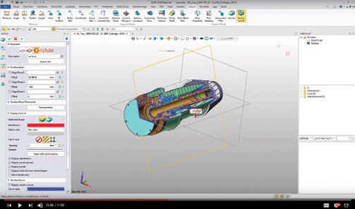
ZW3D includes both CAD and CAM capabilities, making it easy to generate and then simulate and verify the toolpaths and NC code needed to manufacture your parts. Image courtesy of David Cohn via ZWSoft.
When you select a command from the menu, the Manager panel is temporarily replaced by a dialog box with controls and input fields for the specific feature you are creating. These dialogs clearly indicate required and optional settings.
Multiple open files each have their own tab within the graphics area. A toolbar across the top of the graphics area provides quick access to common tools for erasing objects, manipulating the appearance and orientation of models, setting the current layer and so on.
Like most 3D modeling programs, you begin modeling parts or assemblies by first creating a 2D sketch to create a base feature. The program provides a range of tools for parametric modeling based on dimension-driven features, allowing for quick design modifications. When working this way, the program maintains a history tree and you can roll the model back to any point in its development. VX CAD/CAM was one of the first programs to also support direct modeling, allowing users to quickly modify any 3D model geometry without history regeneration. ZW3D continues that tradition and also enables solid-surface hybrid modeling, so users can perform Boolean operations for surface parts directly with solid geometries.
ZW3D makes it easy to import models created in other programs. You can open or import a wide range of formats, including CATIA, Creo and Pro/E, Inventor, NX, Solid Edge and SolidWorks. You can also open AutoCAD DWG files, neutral formats such as ACIS, DXF, IGES, Parasolid, STEP and VDA, and lightweight formats including 3DXML, CGM, JT, OBJ and STL.
A Full Range of Tools
ZW3D includes sheet metal capabilities, including advance unfold and weldment design. Its assembly modeling tools allow for top-down and bottom-up designs. You can edit assemblies and components and manage associated models. The program’s verification tools help ensure the manufacturability of your designs.
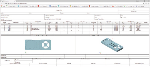
In addition to generating machine code, you can save an HTML operations list that includes machine parameters. Image courtesy of David Cohn via ZWSoft.
As you might expect, the program can easily create associated 2D drawings based on 3D models, with tools for adding dimensions, tolerances and annotations that can be updated automatically to reflect changes to the model. There are also product and manufacturing information tools to add dimensions and annotations directly on 3D objects.
In addition, ZW3D includes specialized tools for dealing with detailed mold designs, such as tools for quickly adding core-cavity parting lines and multi-cavity designs. It also comes with a library of mold base components and standard parts.
All This, Plus CAM
What sets ZW3D apart from most of its competitors is the fact that it integrates CAD and CAM tools in a single package. What’s more, those CAM tools are relatively intuitive and quick to master. The program supports everything from two-axis milling to four- and five-axis simultaneous machining.
Once you have created the desired part in the CAD environment, you can immediately begin programming the toolpath and generate the numerical control (NC) code. Having both the CAD and CAM tools integrated within the same program ensures that everything remains associative—you can easily update toolpaths to reflect changes made to the model.
After shifting to a CAM plan view, the ribbon changes to display CAM-specific tools and the manager panel changes to the CAM Manager tree. You can click the Exit tool to switch back to the CAD environment at any time. More than 40 types of machining operations are included in ZW3D to facilitate efficient roughing, smoothing, finishing and high-speed machining.
For example, you can add the stock from which the part will be milled and then add milling and drilling operations. A series of dialog boxes lead you through each step in the process, with complete control over the tool type, size and other parameters.
You can use ZW3D’s Solid Verify command at any time to simulate any step in the machining process. There is also a flexible toolpath editor that lets you improve machining efficiency without having to make tedious adjustments or modify parameter settings. After making a change, you can recalculate the toolpath with a single click. You can edit all or just a portion of the toolpath.
You can also select a feature within the model and then let ZW3D automatically create the appropriate milling operation necessary to produce the desired results. There are also analysis functions to help detect collisions. Once the toolpaths are complete, ZW3D can generate the NC code. You can also output an operations list as a single HTML file that contains all the process information, including machine parameters and operation times.
The program’s post processor includes more than 70 of the most popular computer numerical control machines, including Fanuc, Haas, Heidenhain, Mazak, Okuma and Siemens. There is the option to add post processors from other companies or purchase customized post processors from ZWSoft.
What’s New
ZW3D 2018 provides a host of new features. User interface improvements include changes to dialog boxes so that you can now see the default unit type. You can now apply changes without ending the current command, so that you can repeat the command without having to reopen the dialog box. The Layer Manager has been enhanced, enabling you to copy and move objects to a new layer and manage and assign layers to categories.
The 2018 release includes a new option to control sectioned components when using the Section with 3 Planes tool. You can now control the three section planes individually and even rotate and hide the planes. A new exclude components option allows you to exclude or include components and section an STL model.
Product manufacturing information capabilities have been improved with the addition of more dimension and annotation types (such as chamfer, arc length, centerline and center mark, and radius/diameter).
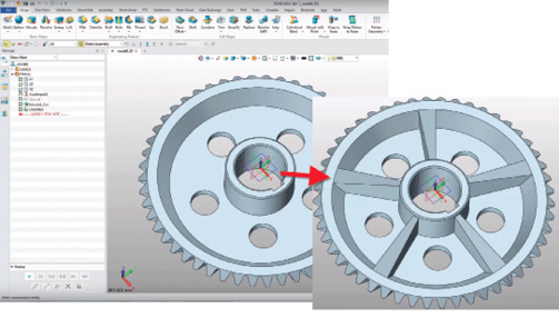
There is also a new associative import function that lets you update imported models without breaking the history. For example, suppose you imported a model from SolidWorks and then added features, such as patterned holes. If the imported part is subsequently updated in SolidWorks, you can reimport the updated model to reflect those changes without losing any of the features you had added in ZW3D. This works with models imported from CATIA v5, Creo, NX, Solid Edge and SolidWorks.
A new unified part and assembly configuration table lets you manage more part configuration parameters, including part attributes, expressions, features and dimensions. You can save configurations to an Excel file, create additional configurations and then import the Excel file.
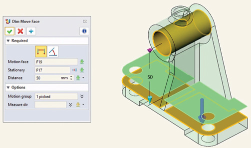
Direct editing functions include a new face overflow control option to match the expected direct editing results. For example, Extend Change Face extends the moving face to close the shape; Extend Stationary Face extends the boundary face to close the shape; and Extend Cap Face automatically adds a cap face to close the shape. The new Dim Move Face tool lets you use dimensions to drive face movements.
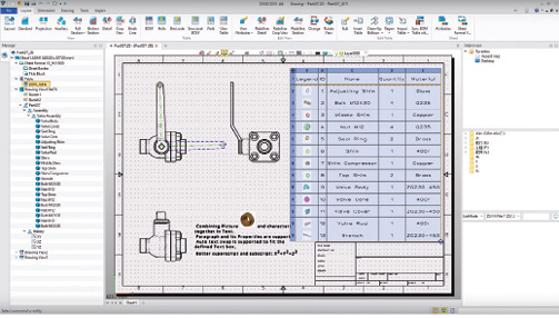
Other enhancements include 2D drafting improvements, such as the ability to include thumbnail images in a bill of material (BOM), support for more date formats, and the ability to include user-defined attributes in BOMs and title blocks.
In the CAM environment, ZW3D 2018 includes improved three-axis operations, such as functionality to add a protect surface for QuickMill finish operations and new options for setting multiple cutting layers for five-axis side cuts.
Multiple Versions
Getting started with ZW3D is easy. The program is available in several versions. ZW3D Lite provides basic 3D modeling capabilities. ZW3D Standard adds freeform class-A surfacing, sheet metal and weldment design. ZW3D Professional adds electrode and mold design. ZW3D Premium includes all these features plus two-axis milling, two-axis turning, three-axis QuickMill, Solid Verification, the tool path editor and the ZW3D post processor.
ZWSoft also offers ZW3D 2X Machining and ZW3D 3X Machining, which include the basic CAD tools of the Lite version plus the two- and three-axis CAM capabilities, respectively. The four- and five-axis machining capabilities are sold as an extra-cost add-on.
ZW3D is available in 14 languages in 32- and 64-bit versions for operating systems, including Windows XP and Vista. You can download a 30-day free trial of the Premium version from the ZWSoft website. The software works beyond the trial period, but the save, print, import, export and post-processor functions become disabled.
ZW3D has a lot to offer, providing features typically found only in much more expensive programs. It offers a reliable, affordable alternative that should be particularly appealing to those who also need to handle the modeling and manufacture of parts and assemblies.
More ZWSOFT Coverage
For More Info
Pricing
ZW3D Lite:
- 6 Months: $350
- Year: $500
- Perpetual License: $2,000
- Perpetual License (w/1-year upgrade): $400
ZW3D Standard:
- 6 Months: $500
- Year: $900
- Perpetual License: $3,000
- Perpetual License (w/1-year upgrade): $600
SW3D Professional:
- 6 Months: $800
- Year: $1,500
- Perpetual License: $5,000
- Perpetual License (w/1-year upgrade): $1,000
ZW3D Premium:
- 6 Months: $1,300
- Year: $2,550
- Perpetual License: $8,500
- Perpetual License (w/1-year upgrade): $1,700
ZW3D 2X Machining:
- 6 Months: $450
- Year: $7,500
- Perpetual License: $2,500
- Perpetual License (w/1-year upgrade): $500
ZW3D 3X Machining:
- 6 Months: $800
- Year: $1,500
- Perpetual License: $5,000
- Perpetual License (w/1-year upgrade): $1,000
ZW3D 5X Machining (add on):
- 3X Post Processors for Premium or 3D Machining: $1,000
- 4X Post Processors for 5X Machining add-on: $2,000
- 5X Post Processors for 5X Machining add-on: $3,000
System Requirements
- OS: Windows XP SP3 (32-bit), Windows Server 2003 (32-bit), Windows Server 2008 (32-bit), Windows Vista (32-bit), Windows 7 (32-bit/64-bit), Windows 8.1 (32-bit/64-bit), Windows 10 (32-bit/64-bit)
- Processor: Intel Core 2 Duo 2GHz or above (or equivalent AMD processor)
- Memory: 4GB minimum
- Disk Space: 6.5GB required for installation
- Display: OpenGL 3.1 or above, NVIDIA Quadro FX 580 or above (or equivalent AMD graphic card); 1024x768 with TrueColor minimum, 1280x1024 with TrueColor or above recommended.
Subscribe to our FREE magazine, FREE email newsletters or both!
Latest News
About the Author
David Cohn is a consultant and technical writer based in Bellingham, WA, and has been benchmarking PCs since 1984. He is a Contributing Editor to Digital Engineering, the former senior content manager at 4D Technologies, and the author of more than a dozen books. Email at [email protected] or visit his website at www.dscohn.com.
Follow DE