When CAD, CAE and CAM Collide

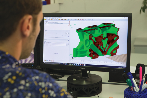
Since acquiring Netfabb in 2015, Autodesk has been busy adding advanced technologies–including enhanced simulation, optimization and advanced toolpath capabilities–that will provide engineers and designers with a broad collection of additive design and manufacturing tools. Image courtesy of Autodesk.
Engineering Resource Center News
Engineering Resource Center Resources


Latest News
July 16, 2018
Design engineers who are a whiz at 3D CAD modeling typically have little aptitude for the CAE tools to run structural analysis on those designs, let alone the expertise to man a CAM solution to gauge manufacturability. But as new manufacturing methods like 3D printing and advanced generative software pave the way for more complex designs, mainstream engineers require a tool bench that combines elements from CAD, CAE and CAM — a convergence now underway thanks to the advent of increasingly powerful computing.
Next-generation, high performance CPUs boasting dramatic increases in both the number of cores and amped up clock speeds, coupled with the accessibility of lower-cost GPU horsepower, create a platform on which design tool vendors can modify their software portfolios to address demand for CAD, CAE and CAM convergence. The industry has traditionally passed through cycles where the focus alternates between making deep-dive improvements to individual CAD, CAE and CAM packages to establishing more robust integration between the individual silos. Today, the pendulum has swung back to an emphasis on integration, and as a result, convergence, according to Ken Versprille, executive consultant for CIMdata, a PLM and engineering consulting firm.
“Teams are always working to produce better products, but it can be difficult to do sometimes because the software fights against them,” Versprille explains. “The fact that you can throw clusters of CPUs in the cloud or powerful GPUs at a problem opens the door to more performance.”
AM Drives CAD, CAE and CAM Convergence
By harnessing modern hardware advances like GPUs, more powerful processors, and new memory media and storage technologies, engineering organizations gain access to the computational horsepower necessary for accelerating 3D modeling applications, enabling real-time analysis and simulation, and rendering complex visualizations. One of the key drivers for convergence of such CAD, CAE and CAM capabilities is the growth of additive manufacturing (AM), which enables the production of previously impossible designs while allowing for new workflows that place an emphasis on optimization.
For example, AM allows for new design concepts that achieve specific structural properties by mixing materials or varying materials usage throughout a part or by redefining multiple parts into a single unit. That kind of design freedom relies on sophisticated optimization studies that require significant compute power.
“When you look at the whole process of optimization, you need to understand all the properties and how they’ll vary in design and you need to do that early in the process—not after the fact,” explains Scott Hamilton, senior worldwide industry strategist, Engineering and Manufacturing, at Dell, who notes that historically, most engineers didn’t have access to the workstation muscle to deliver on optimization in any significant way. “For the optimization process, ideally you want to run thousands of simulations, not a handful, and the limiting factor to doing that has been computational horsepower.”
Moreover, as AM eliminates the many design constraints of traditional manufacturing, engineers need to think differently about design. Tapping new generative design tools to explore lattice structures or to create organic shapes that combine what were previously separate parts into a single entity requires that engineers have access to capabilities that span traditional CAD, CAE and CAM domains, which is more fuel for convergence, notes Stephen Hooper, senior director, business strategy and marketing for manufacturing, at Autodesk. “You can’t separate the design from manufacturing any more without expecting some pretty adverse effects in terms of cost and time to market,” Hooper says.
In response to the need, Autodesk has transformed the way it offers software, shifting from a collection of bundled technologies to providing an end-to-end product development solution directly inside of Inventor, he explains. “We want to provide everything you need for full product development from initial ideation all the way through manufacturing and finish,” he says. On that note, the acquisition of HSMWorks, a CAM plug-in that works with mainstream CAD packages, gave way to Netfabb digital manufacturing capabilities, but also for specific 2.5-, 3-, 4-, and 5-axis milling capabilities to be folded into the foundational Autodesk Fusion 360 offering.
Other leading CAD vendors are following suit. Dasssault Systemes released SolidWorks CAM (SW CAM), an add-on to all desktop versions of the CAD tool that is based on technology from long-time partner HCL. Siemens PLM Software has continuously bolstered the CAM and coordinate measuring machine (CMM) programming capabilities of its NX CAD package, including applications that simplify the creation of smart tool paths. For its part, PTC offers CAM extensions for specifying tools and tool paths along with capabilities for simulating and visualizing material removal directly within the Creo CAD environment.
Looking further down the pike, Desktop Metal, a manufacturer of metal 3D printers, sees opportunity for the advances in computational horsepower, particularly more powerful, less expensive GPUs, to enable on-the-fly checks and course corrections that promote first-time accuracy for 3D prints.
“The goal is to create a closed-loop system that is constantly monitoring what you are creating and compensating in real time,” explains Andy Roberts, head of generative design tools at Desktop Metal. “That’s a computationally expensive task to perform because there’s lots of image and sensor data coming in in real-time. But as the cost of GPUs come way down, it’s realistic to have that kind of processor making sure everything comes out right.”
Voxel-Based 3D Printing, Optimization, and Simulation
Typically, when you work with topology optimization software, you supply the program with loads, stresses, and material characterization, then let the software identify the best shape or geometry that meets your design objectives. But there’s a different kind of optimization that additive manufacturing pioneers — especially those experimenting with large-scale, industrial AM — have been looking for: Given the anticipated stress and loads on a certain shape, what is the best internal structure to use to counteract them while maintain the general outer shell?
 Voxel-based 3D printing with NVIDIA GVDB, where the inside structure is optimized based on stress and automatically generated. Image courtesy of NVIDIA.
In that regard, the introduction of NVIDIA GVDB Voxels at the GPU Technology Conference in 2017 and the updated version 1.1 shown at GTC 2018, offers some tantalizing possibilities. With GVDB-based simulation, the demo showed you could build a program to automatically populate the interior of a 3D model with lattice or honeycomb structures, with varying densities in different regions to account for the anticipated stress loads.
Currently, CAD users prepare the geometry in CAD software, then export the model as STL or another 3D printing file format for printing. “If software vendors begin adopting it, you’d probably start to see GVDB as part of the data flow between STL to the print-preparation tools,” said Andrew Page, NVIDIA product manager. “In longer view, what we’d like to see is CAD applications sending voxels directly to the printer [without going through an intermediary file format] and printing the job based off voxel information.”
Subscribe to our FREE magazine, FREE email newsletters or both!
Latest News


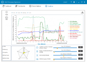
 DPO can optimize hardware settings to maximize performance for many popular software applications. Image courtesy of Dell.