Latest News
January 1, 2012
By Kenneth Wong
In the last several years, sustainability, durability and cost have emerged as the three pillars of manufacturing. In SolidWorks, you can address the first two with Sustainability Xpress (first previewed in 2009, now included with every license) and SolidWorks Simulation. In SolidWorks 2012, you’ll get a new tool called SolidWorks Costing to address the remaining pillar.
Although it’s in pre-release code at press time, in structure and setup, SolidWorks Costing is uncannily similar to SolidWorks Sustainability Xpress. You can use the Costing module to estimate how much it’ll cost to produce a sheet-metal part or a machined part. The software calculates manufacturing costs using a set of preloaded templates with prices for standard sheet-metal and machining operations. (There’s no template for injection-molded plastic parts in this release, but perhaps one is in development.) To get more accurate results, most manufacturers should modify the templates by populating relevant fields with their own materials, known unit costs and supplier quotes from previous transactions.

SolidWorks 2012 marks the debut of SolidWorks Costing, a module you can
use to obtain cost estimates on sheet-metal parts and machined parts.
The module, found under Tools tab, is fairly straightforward. The moment you launch it, it begins calculating your design’s probable manufacturing cost. The software can tell the difference between a sheet-metal and a machined part, so you’ll only get the option that’s relevant to the part found in your modeling window.
Calculations are done based on standard sheet-metal punching or machining operations required to produce the features found in your geometry—for instance, the number of pockets, holes and bends. The results are updated in real time. (OK, “near real-time,” if you want to nitpick, because it does take a few seconds for the software to crunch the numbers.)
Perhaps this is the type of calculation you’re used to doing with pen and paper; perhaps you already have an Excel spreadsheet with embedded formulas that can spit out the same estimates based on manual input. Either way, you’ll find that the ability to automate this grueling process comes with great benefits.
You may, for instance, change the thickness of a sheet-metal part, or switch from steel to iron to find out how it affects the production cost. You may also experiment with removing or adding features to see if you can reduce the cost (sometimes, the feature that drives up manufacturing cost the most is not necessarily what you think it is). Tight integration with a 3D model makes it easy to explore different alternatives. Currently, the module can be used only to estimate costs on parts, but you can get the roll-up cost of an assembly.
Exploded Multi-body Parts
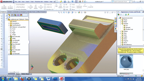
Several releases ago, SolidWorks introduced multi-body parts—parts with more than a single solid body. The easiest way to create a multi-body part is to uncheck the Merge Results option when you’re extruding a sketch profile into a solid volume. This creates a single part with two—or more—independent solid volumes.

In SolidWorks 2012, you can create exploded views of multi-body parts.
Individual solid volumes in multi-body parts behave like subassemblies.
In the new release, you’ll be able to create exploded views of such multi-body parts. When you choose Insert > Exploded View, you’ll get the option to drag and reposition the solid volumes in your part along X, Y or Z axis, as though they were sub-assemblies in an assembly model.
Frozen Features
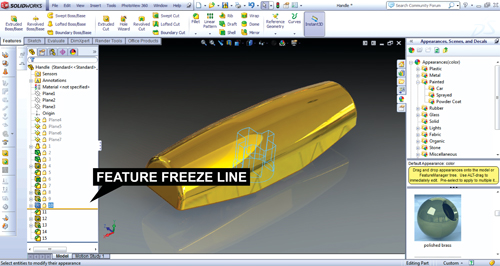
For those who work with complex parts with a lengthy feature history, SolidWorks 2012 offers the option to freeze features. You can activate the tool by going to the application setting options and checking the Enable Feature Freeze box. In doing so, you activate a feature-history marker—a line you can drag up and down your feature history. Once you place the line, features above the line become “frozen.”

Feature Freeze (shown here as a line marking the freezing point in the history)
prevents unnecessary geometry rebuild during edits.
This is a good method to prevent unnecessary geometry rebuilds when you’re making edits that don’t affect earlier features. However, effective use of this tool requires a thorough understanding of parametric (or feature-based) modeling. If you’re making subsequent edits that reshape earlier geometry, freezing earlier features may produce unintended deformations and error messages.
Balloons, Punch Tables and Large Models
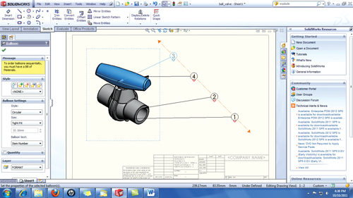
If you have a series of balloon-nested text strings with crisscrossing arrows, you’ll probably like to use the magnetic line to untangle the mess. As the name suggests, the magnetic line behaves as a line to which you can stick your balloons. By dragging the balloons within close proximity to the magnetic line you’ve drawn, you can align the ballooned objects into a neat stack, pinned to the invisible line.
With sheet-metal parts, SolidWorks 2012 gives you the option to include Excel-style punch tables in the drawing view of the flattened pattern. The table can contain punch IDs, quantities, locations of the holes (measured from X and Y axes), angle and other attributes.

The Magnetic Line function helps you align your ballooned text by anchoring
them on an invisible line.
For those who work with large assemblies, SolidWorks 2012 provides a way to load them faster with the Large Design Review option (available as one of the drop-down options when you’re opening a file). With this mode, you can load the model—and its sub-components—into the program window as display-only geometry, which demands less memory and processing power. It’s a useful tool for those who need to inspect, but don’t need to modify large assemblies.
Looking Beyond 2012
SolidWorks is going through a leadership change. Austin O’Malley, one of the original developers of SolidWorks (dating back to version 95) has left his post as vice president of research and development. O’Malley shepherded the company through eight major product releases. The post vacated by O’Malley is being filled by Gian Paolo Bassi, founder and CTO of RIWEBB. Bassi’s past roles included vice president and chief technology officer of ImpactXoft, director of think3, and program manager at Computervision.
SolidWorks 2012 is a notable upgrade, particularly for its debut Costing module. Other enhancements—such as Large Design Review mode and Magnetic Line—are expected to make assembly edits and drawing production easier and faster. Feature Freeze, when used appropriately, will save time by preventing unnecessary geometry regeneration. However, the new version doesn’t sufficiently address an area where SolidWorks’ rivals have been making consistent improvement: direct modeling. Bassi may change this in a subsequent release.
When asked to describe his vision for SolidWorks for both the near future and long term, he replied, “Models need to have more freedom in the way they are designed, modified and behave. I will bring hybrid methodologies beyond geometric parameters to functional design.” (Editor’s Note: His reply is part of a Q&A published as a blog post titled “SolidWorks in Transition,” which is available here.)
Kenneth Wong is senior editor of Desktop Engineering. Contact him via [email protected], at deskeng.com/virtual_desktop or via Twitter @KennethwongSF.
MORE INFO
Subscribe to our FREE magazine, FREE email newsletters or both!
Latest News
About the Author
Kenneth Wong is Digital Engineering’s resident blogger and senior editor. Email him at [email protected] or share your thoughts on this article at digitaleng.news/facebook.
Follow DE


