Rolls Royce Works with Student Team to Create 3D Printed Jet Engine Model

The Xplorer-1, side view. Image courtesy of 3D Hubs.


Latest News
April 1, 2018
By George Fisher-Wilson
There’s a shortage of engineering students and in STEM (science, technology, engineering and mathematics) subjects generally. Whether it’s developing rockets to Mars, the new future of public transport or a bridge, society needs engineers to make it happen. This team of students is looking to fix this shortage by getting more potential engineers involved and interested in this field. 3D Hubs Student Grant finalist JetX represents a team of aerospace engineering students working with Rolls Royce to create the world’s first functional 3D printed jet engine model that will provide instant design feedback and show people studying engineering doesn’t mean you’re glued to a textbook.
The project started back in 2013 at the University of Glasgow when Chris Triantafyllou, the president and founder of JetX, spotted the need for more hands-on learning to get people engaged with the subject. Alongside this, he saw two important skills for future engineers to master but with no outlet to gain direct experience:
- Design for assembly.
- Simulation analysis.
By building such an ambitious project and working with Rolls Royce, JetX hopes to show that engineering isn’t just writing down theorems and mathematical equations but about making a real impact with the work you do.
The functional X-plorer 1 model is 75 cm long, with span diameter of 27 cm, and weighs in at 8.1 kg. Over 50 young engineers have been tirelessly working on the project, developing over 965 3D printed parts, 300 fasteners and 10 integrated sensors into one high-bypass turbofan model.
Design Process
The entire design has been done from scratch with every piece modeled in line with current aeropropulsion theories. The process of design, consultation, analysis and execution is giving this team of young engineers hands-on training to become the next generation of innovators in the aerospace industry.
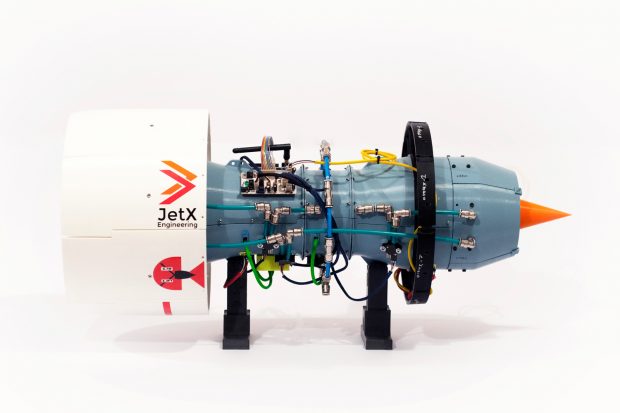 The Xplorer-1, side view. Image courtesy of 3D Hubs.
Multiple considerations were taken into account when building the Xplorer-1. Triantafyllou explains where it began. “The first step in optimizing the design is to perform computational analyses to investigate how the flow changes throughout the engine, as well as the effect that specific forces and loading conditions have on the parts. When several designs are available for one part, CFD analyses are performed with tools that include SolidWorks Flow Simulation, ANSYS Fluent & Star CCM+ on single stators, rotors or multistage segments to assess which one performs the best.”
Additionally, the JetX team also carries out finite element analyses to identify high stress concentrations and assess whether failure is likely under different loading conditions. The centrifugal forces generated can be significant even on a model of this size, and failure scenarios are also modeled to assess whether an impact would be contained.
Once designs are completed, the parts are produced on a 3D printer. JetX currently uses a desktop FDM printer using materials such as PLA (polylactic acid), ABS (acrylonitrile butadiene styrene), nylon, PETG (Polyethylene terephthalate glycol-modified) and more for testing. The model was made exclusively from FDM (fused deposition modeling) printed parts, with the shortest print lasting just 7 minutes and longest being over 58 hours for the main PCU casing.
3D Printing Employed
3D printing was used for the project, as alternative manufacturing technologies such as CNC would have been far too expensive for the amount of one-off parts the team needed.
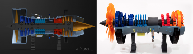 The original CAD model of the Xplorer-1 next to its 3D printed counterpart. Image courtesy of 3D Hubs.
“The transition from CAD to part is simpler and the amount you spend goes a long way with 3D printing especially when using an FFF 3D printer,” Triantafyllou explains.
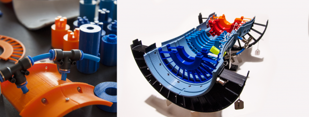 A selection of 3D printed parts and a cross-sectional look inside the Xplorer-1. Image courtesy of 3D Hubs.
A key advantage to using an affordable manufacturing method was JetX’s ability to rapidly change parts when they found new optimizations with their testing. An example was when a connection to the shaft was technically too weak as a 3D printed part, but they needed a quick solution to prove it could sustain the load.
Triantafyllou highlights how 3D printing kept them agile: “It took 21 prototypes and only 7 days to get to the part we needed; using another manufacturing method would have meant months and the cost would be £1,000’s or even £10,000’s.”
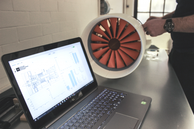 The EMS in action while the Xplorer-1 is set up for testing. Image courtesy of 3D Hubs.
The internals of the Xplorer-1 feature a custom-built engine monitoring system (EMS) in which everything was developed in house including the PCB designs, purpose-built software and user interface. The EMS consists of wireless transceivers, two mbed micro-controllers, temperature sensors, differential pressure sensor, LED rotational speed sensors, a vibration sensor and an airspeed sensor.
Final Result
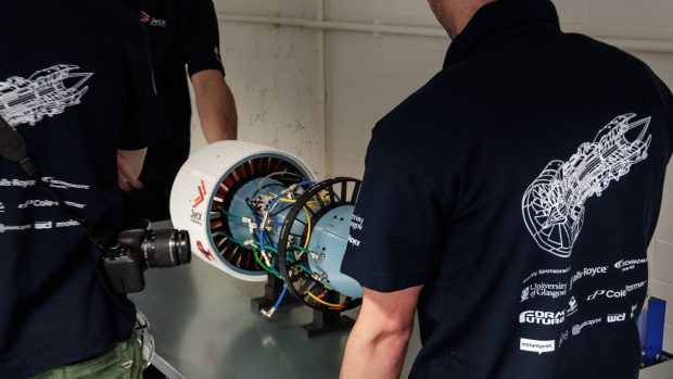 The back of the Xplorer-1: showing off its intricate wiring with the JetX team around it. Image courtesy of 3D Hubs.
All of this culminates in the creation of a fireless engine in which students can pass compressed air through the engine to take measurements with the wide array of sensors. You can then see the performance of the engine in front of you and electronically, making it easier to analyze each stage of the flow. This leads to more iterations and parts to be created, and through this process the team continues to develop their skills for future career paths in engineering.
The next step for the project will be to first continue to iterate and improve the engine, not only in its performance but, in the way it provides data on its performance. Rolls Royce has joined the project to help with the technical side of things including advising on industry practices to try to get the engine’s iterations as close to the real process as possible.
Secondly, the project will look to further its engagement in STEM fields, encouraging students to get outside of the lecture environment and to apply their learning. Eventually, Triantafyllou would love to see the project turned into a competition where universities compete to build the most efficient engine to inspire others and to build on the success they have had in Glasgow.
George Fisher-Wilson is a blogger for 3D Hubs.
Subscribe to our FREE magazine, FREE email newsletters or both!
Latest News