Measuring Right for All Your Needs, Part 2
Enterprise metrology closes the loop with MCAD. Part 2 of 2: Paperless inspection planning, a new MCAD synergy.


Latest News
November 1, 2005
By Steve Logee
The emerging discipline of Enterprise Metrology (EM) promises systemic improvements in manufacturing efficiency by making dimensional measurement programs, data, analyses, and reports compatible across a broad range of measurement systems and readily accessible throughout all phases of manufacturing.
The six areas where EM is capable of delivering substantial synergies were outlined in the previous installment of this article. In Part 2 we will see how EM can, at last, close the information loop with MCAD, which is at the very beginning of the manufacturing process. Before this can happen, however, a significant disconnect, one occurring at the very beginning of the evaluation process, must be repaired. 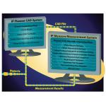
› › The PC-DMIS Inspection Planner Suite from Wilcox Associates leverages the GD&T capabilities of some advanced MCAD systems (e.g., Unigraphics, Solid Works, CATIA) to develop and embed electronic inspection plans within an MCAD model. These can be automatically interpreted at a CMM and other measurement device workstations and used as the basis for generating inspection programs.
The latest MCAD software lets designers embed everything a manufacturing engineer needs to know into their models. So, CNC programmers use MCAD models to build cutting programs quickly and efficiently. Unfortunately, the design intent (geometric dimensioning and tolerancing—GD&T—information), which can also be part of the models, is not readily accessible to the quality engineer. In most cases, this data arrives in the form of marked-up, 2D drawings.
The inspection system programmer manually enters this data into the program when it is available. If it isn’t supplied, he must guess at these essential values or insist that the designer or someone else provide them. In either case, this manual process is very inefficient and prone to error. What’s more, early discontinuity between MCAD and the part evaluation process impedes the flow of evaluative information that could shorten part and manufacturing process lead times.
Tale of Two Modules
Fortunately, this disconnect can be fixed using the GD&T capabilities of many new MCAD software programs to embed design intent within the MCAD model. For example, two software modules created by Wilcox Associates of North Kingstown, RI, automate the capture of design within MCAD and automatically extracts that information and incorporates it within a CMM (coordinate measuring machine) program.
The Inspection Planner Suite consists of two distinct modules, IP Planner (resident in MCAD) and IP Measure (resident in Wilcox’s PC-DMIS measurement software).
IP Planner is an add-on software module for MCAD systems. It allows design engineers to define plans containing all the information relevant to a part’s inspection. In essence, IP Planner creates a virtual, marked-up blueprint of a component. It makes use of the MCAD system’s GD&T capabilities in allowing design engineers to select the features to inspect and the methods for inspecting them. It also gives them tools for defining datums, dimensions, and reporting requirements. To maintain a consistent look and feel for users, these new capabilities are fully integrated into the host MCAD system.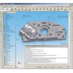
‹ ‹ IP Planner is an add-on module that allows design engineers to use the MCAD system to define an inspection plan containing all the information relevant to the inspection of the component. It creates a virtual, marked-up blueprint of the part, making use of GD&T capabilities in defining each feature to be inspected and the method for inspecting it. Click on image to enlarge.
Where the IP Planner module creates the inspection plan at the measurement device, the IP Measure module puts it to use. Upon receiving a plan, IP Measure uses it to create an inspection program automatically.
The process goes like this: The software lays down a pattern of hits on each feature according to a user-defined rule set, develops a datum scheme, creates a probe path among the features, optimizes the probe path, dimensions the features, and creates a template for reporting the measurement results. When working with a 3D solid model, it also uses its collision detection algorithms to check for any interference between part and probe. The process is direct and paperless.
Since the plan is electronic, there is no chance of losing or misconstruing design intent in the process. In addition, IP Measure develops a part program specific to the machine on which it will run. This means that the inspection planners do not have to know anything about the machines that will be inspecting the parts. All they have to know is what needs to be inspected. PC-DMIS and IP Planner Suite work not only with CMMs, but also with probe-capable CNC machines, vision systems, articulating arms, and other measurement devices.
Paperless Benefits
Integrating inspection planning into MCAD design makes good sense for many reasons:
• The Logical GD&T Source—Since there is a definitive link between design intent and manufacturability, the MCAD system, where designers do their work, is the most logical place to develop an inspection plan.
• Direct Information Flow—With IP Planner in the MCAD system, engineers can make inspection planning an integral part of their design process. This assures that there is a flow of metrology information from design through production and inspection by creating a direct link between design intent and the inspection function.
• Automating Inspection Programming—The sooner critical design information is electronically encoded, the sooner manual functions, such as conventional point-and-click inspection programming, can be eliminated. Using the IP Measure module on a CMM with PC-DMIS software, CMM programmers automatically generate part programs from Inspection Planner files. The time needed to build part programs using this approach is a fraction of what is necessary using conventional methods. It’s no longer necessary to input motion or measurement commands into inspection programs, and it’s not necessary to spend time trying to interpret blueprints and enter the resultant information. This minimizes or entirely eliminates the opportunity for introducing errors while freeing up staff whose skills can be better used elsewhere.
• Managing Changes—A major benefit of this approach is that inspection requirements and MCAD models become part of the same entity. This means that modifications to MCAD models automatically generate changes in its Inspection Plan, and that these generate changes in the associated inspection programs. In cases where PC-DMIS links directly to the MCAD system with a direct CAD interface (DCI), this happens automatically. When it’s not, the user must reload the MCAD file into PC-DMIS. In either case, this solves a major problem in change management since a significant number of manufacturing errors are a result of production and quality departments not being aware of design modifications.
More Power to MCAD
What’s in the future for MCAD integrated inspection planning? Quite a bit, it turns out. Developers are exploring all sorts of interesting ideas. One, applicable to prototyping and reverse engineering applications, is to use the inspection plan as a medium for putting part measurement information directly into the MCAD model. This requires the use of a DCI, which provides a real-time window between measurement systems and the model in the MCAD system. This can be a powerful tool for manufacturing process development, although it comes at the price of requiring a dedicated MCAD seat.
› ›
Where the IP Planner module creates the inspection plan, the IP Measure module puts it to use. The software lays down a predefined pattern of hits on each feature, creates a probe path among them, optimizes it, dimensions the features, and creates a template for reporting the results. Since the plan is conveyed electronically, there is no chance of losing or misconstruing design intent. Click image to enlarge.
By providing universal tools for sharing data, measurement programs, and analytical information, EM closes the loop between MCAD and manufacturing and opens the door for designers to make major contributions to the streamlining of manufacturing process development, and the realization of systemic improvement in quality and efficiency.
Steve Logee is the director of business development for Wilcox Associates of North Kingstown, RI, manufacturers of PC-DMIS 3D measurement software. Send comments about this article via e-mail by clicking here.
Product Information
Wilcox Associates
North Kingstown, RI
Click here to access a video on Enterprise Metrology.
Subscribe to our FREE magazine, FREE email newsletters or both!
Latest News
About the Author
DE’s editors contribute news and new product announcements to Digital Engineering.
Press releases may be sent to them via [email protected].


