Material Insights into Additive Manufacturing
Use of multiscale material modeling and simulation software is helping expand role of additive manufacturing.
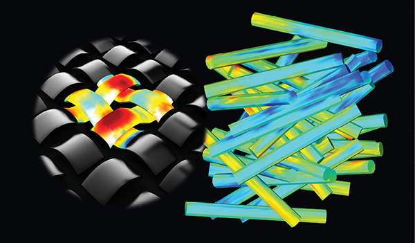
Fig. 1: Multiscale material modeling and simulation tools aim to provide insights into the interactions of microstructural features and the AM materials and processes that are involved. Microstructures can take on forms such as a weave (left) or short fibers oriented in random directions (right). Image courtesy of Siemens Digital Industries Software.
Latest News
June 15, 2021
Additive manufacturing (AM) stands at a crossroads. No longer seen primarily as a prototype-building technology, AM has taken on a role in manufacturing as a key technology enabling on-demand manufacturing. In doing so, however, it has pressed modeling and simulation software developers to take new areas of analysis into mainstream design.
With AM now a prime candidate for fabricating precision and safety-critical components for aerospace and manufacturing applications, it is no longer enough for engineers to know the resulting material properties after the AM process. Increasingly, they also need insights into how the properties came about and how they impact the performance of the printed part.
To address this need, engineering software developers are offering a technology called multiscale material modeling and simulation software. These platforms aim to provide greater understanding of the connections between materials, 3D printing processes and part performance.
Now, the question is to what extent can these software platforms enhance AM design and fabrication, and in what areas must the software grow to maintain additive technology’s expanding role in manufacturing?
Design-Material-Process Connection
To understand what multiscale material modeling and simulation can and cannot do, engineers must recognize the interdependencies of a print job’s design, material and fabrication processes. Ultimately, the quality and performance of the printed part is determined by the properties and interactions of these three elements. The complexities of these relationships are amplified by what sometimes seems to be an infinite number of variables.
“One can take the same geometry, use the same additive manufacturing machine, with the same settings, and still obtain different material properties on the component just by orienting the component differently or using different supporting structures,” says Hunor Etele Erdélyi, research engineer, senior manager at Siemens Digital Industries Software. “These will implicitly impact the local temperature histories, potentially leading to different local microstructures and defects (Fig. 1).”
Thus, it’s critical to consider the design, printing process and material properties together to accurately assess the performance of the 3D-printed component. Omitting any of the elements or properties invariably leads to unsatisfactory results. This is particularly true at the design level.
“If the models do not account for nonlinear properties—such as temperature and process-dependent material properties—they cannot produce a design that delivers superior quality and performance,” says Ehsan Toyserkani, director of the Multi-Scale Additive Manufacturing Laboratory at the University of Waterloo in Ontario, Canada.
Informed Decision-Making
Once this process-property-performance link is established, however, engineers can see the effects that design and manufacturing decisions on material properties and the component’s performance. This enables engineers to search for design alternatives—using technologies such as generative design and topology optimization—to use source material more effectively while optimizing designs and fabrication parameters. In addition, when the properties of a material are accurately known, that knowledge enables the most efficient use of that material to create a safe part.
An industry case study that involves Stratasys demonstrates this idea. “Multiscale material modeling and simulation enabled Stratasys to iterate designs and parameters using simulation instead of devoting time and materials to testing via printing,” says Olivier Lietaer, additive manufacturing business development engineer at Hexagon. “It also used simulation to anticipate printing problems by evaluating the impact of printing direction and location, and to explore the effects of process parameters on process quality and part fidelity.”
In this case, the engineers found a correlation when comparing results of warpage simulation with 3D scan measurements of the printed composite tool. As a result of material modeling, advanced simulation capabilities helped the company reduce warpage from 0.5 mm to less than 0.1 mm, or by about 20%, according to Lietaer.
Multifaceted Analysis Required
To achieve results like those in the Stratasys use case, it is important to consider that additive processes shape mesoscale and microscale material microstructures. These structures dictate the effectiveness of material behavior at the part, or macroscale, level (Fig. 2).
Advanced modeling and simulation tools must factor in multiple microstructural features and the AM materials and processes that create them. For instance, homogeneous materials, such as polymers or metals, exhibit anisotropy during additive processes, often assuming material properties like stiffness and strength in the direction that the 3D-printed layers are stacked. Thermal processes affect the succession of layers that comprise a 3D-printed part. These processes can drive microstructural changes in metals and define interlayer-adhesion quality in polymers.
An example of interlayer-adhesion effects is seen with polyether ether ketone (PEEK) and poly ether ketone ketone (PEKK), which are semi-crystalline materials that offer ideal temperature resistance and fatigue properties. The catch is that these properties can be achieved only if the materials are fully crystallized. Simulation can predict material properties—such as the degree of crystallinity of the interlayer adhesion in function of the material and process setup—and help engineers optimize material and design performance. Inadequate processes can cause an agglomeration of partially molten particles on part surfaces, which can result in rough finishes and diminished fatigue performance.
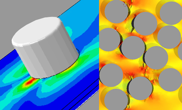
The link between material and process is even stronger for composites, and especially with material extrusion systems. In these cases, the printer-head deposition strategy, or toolpath, drives fiber orientation, which is largely responsible for the part’s mechanical behavior (Fig. 3).
Engineers can use these types of insights to predict AM build-parameter effects on key part characteristics, such as residual stress, surface roughness and resulting microstructure.
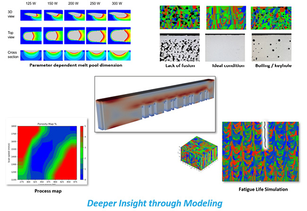
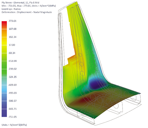
“AM build parameters—such as laser intensity, laser speed, hatching space, powder-layer thickness and orientation of build—can be considered as part of the process modeling of the more advanced solutions,” says Jingfu Liu, chief scientist for additive manufacturing at Sentient Science. “These predictive modeling tools usually agree quite well with experimental results for both microstructure and performance across multiple geometries, AM materials and loading conditions (Fig. 4).”
Application Considerations
Another element that influences material models and simulations is the 3D-printed component’s build case.
Take for example a fatigue-critical metal component produced by laser powder bed fusion (LPBF). Here, the fatigue is driven by the component’s geometry, applied loads and local material properties, including process-induced fatigue-influencing factors like surface roughness and defects. In this case, surface roughness will most likely have the greatest impact, followed by the sub-surface defects (e.g., pores, cracks and inclusions), and the material microstructure.
To make modeling these cases even more difficult, fatigue-influencing material properties are typically local properties, which change from one region of the component to another. In these cases, the calculations must also treat the material properties in a local manner.
“Using simulation technology that can relate the different local fatigue-influencing factors induced by the additive manufacturing process to the fatigue performance of the component enables the engineer to concurrently analyze the impact of the design and the manufacturing itself on the fatigue of the component,” says Erdélyi. “It can turn out that just by reorienting the component within the build can produce favorable local properties in a fatigue hot spot that will subsequently lead to improved fatigue life.”
Challenges and Shortcomings
Multiscale material modeling and simulation software elicits a lot of excitement, and holds benefits for design and manufacturing engineers. A balanced evaluation of the current capabilities of this nascent technology, however, spotlights challenges that evoke a more guarded response. Many of the concerns arise from the fact that AM is still in the relatively early stages of its development.
“The maturity of additive manufacturing technology is a notable challenge to predicting anisotropic behavior, especially considering that material performance is often dependent upon the characteristics of printers,” says Lietaer. “Defects such as material porosity and residual powder are variables that can’t be predicted by even the most advanced simulation. Complex thermal processes that influence material properties, such as material microstructure, metallurgical characteristics, interlayer adhesion, and crystallinity, make anisotropy challenging to predict simply by virtue of their inherent intricacy.”
Not all shortcomings, however, take the form of technology constraints. Some are associated with the practicality of the technology.
“It is possible to link processing parameters and materials to microstructure,” says Brent Stucker, distinguished engineer at Ansys. “But it is currently inefficient and time-consuming to try to predict those microstructures everywhere in a part simultaneously. As such, there is still a disconnect between the ability to predict microstructural aspects of a part and their effects when scaled up to an entire part.”
Part of this challenge stems from the sheer scale of the required analysis, which spans different time and length scales.
“A component produced by LPBF has a typical size of 20 to 30 centimeters and can have kilometers of laser weld tracks, produced over many hours, while the melting and solidification of the metal happens at a scale of approximately 100 micrometers in a fraction of a second,” says Erdélyi.
Another challenge stems from the fact that these are multiphysics applications that require a diversity of simulation methods to be able to link the material process to the resulting material properties and their impact on part scale performance. In addition, some of the different tools and methods used in these applications have yet to be integrated in a streamlined end-to-end simulation platform that enables efficient use and to manage the different models.
Compounding the complexity issue is the fact that these applications can require significant computational resources.
“Design tool developers and users make trade-offs about how a tool will accurately represent the design data and the anisotropic behavior of the material,” says Seth Hindman, senior manager, Product Strategy and Management, of Autodesk. “Anisotropy introduced by mixed materials or spatial variation can be intense to calculate by explicit modeling kernels. Conversely, implicit representations of models that enable real-time modeling performance are difficult for analysis and manufacturing tools to directly leverage.”
Some software providers, however, aim to overcome these hurdles by connecting their design and engineering tools to the cloud, offloading intense calculations and opening the door for engineers to explore variations.
That said, these computational resources can come with a hefty price tag, particularly when the engineer seeks rapid, high-fidelity part qualification via modeling.
“The expensive computational cost to model the layer buildup process limits the practical applications of most predictive approaches,” says Behrooz Jalalahmadi, vice president of additive manufacturing and life prediction technologies at Sentient Science. “The AM industry requires efficient computational approaches that can be performed in an affordable computational manner—in terms of both cost and time.”
A Place in the Thread?
No discussion of a software platform’s strengths and weaknesses is complete until it addresses how well the program fits into the digital thread. In the case of multiscale material modeling and simulation platforms, the answer to this question is essentially an extension of challenges around complexity.
The reality is that it will not be easy to integrate all the required simulation tools into one digital thread because of the multiscale, multiphysics and multi-attribute aspects. To meet this challenge, software providers will have to increase the breadth and depth of their offerings.
“The challenge is to expand and enhance the scope of material definition within the digital thread,” says Hindman. “For example, the majority of toolsets expect the answer for a material and its associated material properties to be discrete. Going forward, these systems will need to be able to tackle the answer to this question based on numerous variables and defined criteria.”
These modeling and simulation platforms are certainly works in progress, and their growth and enhancement are closely linked to general AM technology. The software providers, however, still must improve their platforms’ interoperability and connectivity if they plan to be a contributing part of digital thread.
“Additive manufacturing has long moved past the state of being just for prototyping in many industries, so the imperative is to connect workflows and the digital thread in an actionable way to the shop floor so that test, metrology and serial production data can be used to validate, correct and improve design choices and manufacturing processes,” says Toyserkani.
More Ansys Coverage
More Autodesk Coverage
More Hexagon Manufacturing Intelligence Coverage
More Siemens Digital Industries Software Coverage
Subscribe to our FREE magazine, FREE email newsletters or both!
Latest News


