Making the Right Connection Can Lower Costs
Attractive, low-cost, high-speed alternatives to GPIB are well suited for interconnecting computers with test instruments.
Latest News
October 1, 2004
By Marsh Faber
Since October of 1972 the IEEE-488 bus, commonly known as the general-purpose instrumentation bus (GPIB), has been the standard interface for connecting test instruments to computers. Within the microcosm of the test and measurement industry, GPIB is still a useful technology but, over the years, other more widely accepted I/O options have been developed. Compared to these newer interfaces, such as LAN (local area network) and USB (universal serial bus), standards like GPIB and MXI (multisystem extension interface) seem almost proprietary. Engineers today are examining this expanded list of I/O options to find cost-effective interfaces for their test-system applications.
 To pick the right interface for your test system, it’s important to examine why universally standard I/Os may be preferred over those found primarily in test and measurement. Whether you plan to use your test system for RandD, design validation, or manufacturing, it is likely that you program and control your system with a PC. Most PCs offer built-in USB and Ethernet-based LAN connections. Much faster than previous PC I/O technologies, these industry-standard technologies are now more suitable for automating and controlling test-and-measurement instruments.
By choosing one of these industry-standard interfaces you can build more longevity into the system while saving time and money and reducing the headaches of assembling your test system.
Benefits of InterfacesSome benefits of these I/Os are immediate and obvious. For example, the computer industry employs thousands of engineers who work continuously to improve the throughput rate, latency, and data integrity of these interfaces. So industry-standard interfaces are likely to continue to improve more rapidly than proprietary interfaces. Once deemed inadequate for test and measurement, these interfaces are now completely viable thanks to the efforts of people in the PC industry. Following the current model for modern PC peripherals, PC industry-standard I/O will eventually make it easy to interchange test instruments with others from a variety of manufacturers, and will increase the chances that future software can take advantage of the I/O syntax.
The proprietary interface cards available from instrument manufacturers are expensive, with price tags typically in the neighborhood of $500 to $1,500. They require you to open up your PC housing to install them and, should there be no vacant expansion slot, you might have to replace the entire computer.
Because of the inherent advantages of industry-standard I/Os and customer demand, instrument manufacturers have begun adding LAN and USB interfaces to their test equipment. For example, the new Agilent N1912A power meter introduced this past July includes LAN, USB, and GPIB interfaces.
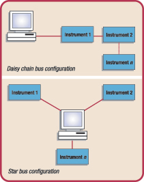
 Figure 1: A GPIB bus can be configured in either a daisy-chain (above) or a star topology (below)—or the two configurations may be intermixed.
The Common GPIB GPIB is the most common interface for programmable test-and-measurement equipment. It is still one of the best choices if you want to maximize throughput for a variety of data block sizes. It is a parallel bus that permits up to 14 devices to be connected to your PC. You can use either a star or a daisy-chain configuration for connecting multiple instruments (see Figure 1, above), but cable length is limited to 2 meters (multiplied by the number of devices) up to a maximum length of 20 meters.
You can achieve data transfer rates of more than 500kBps (4Mbps) on a GPIB bus if you limit bus cable length to 1 meter per the total number of devices up to a maximum length of 15 meters. Longer cable lengths reduce the maximum data-transfer rate.
When you use GPIB, configuring the instrument I/O bus is a relatively easy task. However, each instrument on the bus requires a unique address. This means that you may have to change an instrument address manually when you configure your system.
GPIB does have some other drawbacks: GPIB cables and connectors are large, bulky, and relatively expensive. And because GPIB isn’t a standard built-in PC interface, you will be obliged to open your PC housing and install an interface card in one of your PC’s expansion slots.
GPIB’s major advantage, though, is that it is well understood. Subtle issues like EMI and radiated susceptibility have been worked out over the years.
To communicate with instruments over GPIB, you do need to install an I/O software package. Plug and Play drivers, IVI-COM drivers, virtual instrument software architecture (VISA), and standard instrument control library (SICL) are examples. These packages support popular languages such as C and C++, Microsoft Visual Basic 6.0, Visual Basic .NET, National Instruments’s LabView, Agilent VEE, and others.
If you want to use your existing GPIB instruments in a rack-and-stack test system, you don’t necessarily need to use GPIB as your interface. For example, Agilent offers converters—USB/GPIB and LAN/GPIB—so you can use your GPIB-equipped test instruments with USB- or LAN-equipped PCs. This eliminates the need to install a GPIB card in your computer.
Multiple Instruments via USBUSB is a serial interface bus capable of data transfer rates of approximately 12Mbps for v1.1, and up to 480Mbps for the newer version, 2.0. In addition, v2.0 is fully backward-compatible with v1.1. The only difference is the data transfer rate.
USB is capable of supporting up to 126 devices on a given interface. As mentioned earlier, GPIB-based systems require unique instrument addresses, whereas USB provides this function automatically. Many USB instruments are equipped with a single USB connector, so multiple devices cannot be daisy-chained together. Instead, you need a hub to connect the various USB devices to your computer (see Figure 2, below).
 Figure 2: USB configurations with a single device (above) and with multiple devices connected through a hub (below).
Hubs provide expansion capability, enabling multiple devices to be connected to a single USB port. These hubs are transparent to most controllers and can be cascaded up to five deep.
Using hubs in your system offers several advantages: Many USB hubs include LED status lights that indicate which port is connected. Also, a hardware failure at the interface to one instrument, such as a shorted line, is unlikely to cause an entire bus to fail. This makes troubleshooting an I/O interface in a large system with many instruments a much easier task than having to disconnect one device at a time to localize the fault—as is the case with a GPIB-based system.
Ubiquitous LANYou can also connect your test-and-measurement instruments to a PC via a LAN interface. Ethernet LANs are widely available at industrial and commercial sites and most PCs found in these facilities are already connected to a LAN. As a result, Ethernet-based LAN interfaces for test equipment are likely to become even more common than USB connections. Ethernet-based LANs commonly support data rates of 10Mbps to 100Mbps, and some even operate at up to 1000Mbps.
LAN interfaces share a number of features with USB. They both operate in serial mode, and both use relatively small and inexpensive cables and connectors—especially when compared with the connector of GPIB.
You will probably need an Ethernet hub to interconnect multiple LAN instruments in a test system; however, Ethernet hubs are readily available today and are relatively inexpensive. Many provide network status or activity indication with a series of LEDs.
Ethernet-based LAN devices typically need to be configured to operate properly on a network. However, instruments that support dynamic host configuration protocol (DHCP) provide the capability for test instruments to configure themselves automatically to operate on a network, if these services are available on the network.
Compared to a USB network, connecting instruments to your PC via a LAN is not as straightforward as simply plugging in a USB device. You can connect LAN-enabled instruments several different ways. They may be connected directly to a site LAN whether it is a workgroup LAN, intranet, or enterprise LAN, or they may be connected to a private LAN.
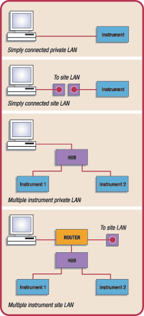
In private LAN configurations, your PC and your test instruments are connected to each other via the LAN, but they are not connected to a site LAN. In the simplest private LAN configuration, which consists of a controller and only one instrument, you would use a crossover cable, rather than the standard LAN cable, to make the proper connections (see Figure 3, below).
 Figure 3: Single and multiple instrument configurations can be connected to private LANs and site LANs.
For all other setups, you can connect instruments to the LAN either with a conventional LAN cable or through a wireless adapter. Wireless routers and hubs also are available, as are wireless USB-to-LAN interfaces. (A discussion of LAN and remote access can be found in Test System Development Guide: Computer I/O Considerations Application Note 1465-2, http://cp.literature.agilent.com/litweb/pdf/5988-9818EN.pdf.)
Which I/O interface to use?To decide which I/O interface or interfaces you should use in your test system, you will need to consider many factors. These include data transfer rates and block sizes, setup time, as well as costs for cables, routers, hubs, and PC I/O cards. Other factors include I/O driver availability and programming requirements, as well as the need for possible remote system access.
Don’t worry if you have a mixture of older GPIB instruments and newer instruments with other built-in interfaces. Today’s advanced software tools that include VISA technology eliminate the need to talk to different kinds of I/O in different ways. A minor change to a single line of code is typically all that is required.
Do not mix interfaces on a single instrument—the input and output must be on a single interface—and make sure your software drivers know which instrument is using which interface.
Be aware that individual I/O bus specifications for data transfer rates usually indicate only the theoretical maximum transfer rate. The actual, achievable data transfer rate for any given system depends on a number of factors. These include PC microprocessor speed, PC software and driver overhead, data type, cable length, I/O card hardware, and instrument-specific hardware and firmware.
Often, implementation cost is an important consideration in selecting an I/O interface for your test system. New PCs typically have several USB ports built in, but GPIB interfaces often require a card that you must purchase separately. GPIB cards usually cost several hundred dollars and, if needed, LAN cards usually sell for $10 to $50. Also, if you plan to use USB or LAN interfaces to connect multiple instruments in your system, you will need hubs. These hubs can cost from $25 to $100 each, depending on features and the number of ports they support.
Consider the cost of the cables for your test system. GPIB cables are relatively expensive, ranging in price from $25 to $100 each, depending on their quality and length. USB cables, on the other hand, range from $8 to $30. LAN cables are typically the least expensive, costing less than $10. Some can be found for as low as $3, but be aware that using unshielded cables could allow EMI emanations that can impact test results, especially in an RF system.
An informed ChoiceCompute the interface cost for your proposed test system. You can make useful cost comparisons by assuming that all test instruments are able to support any of the three interfaces. Today, few test instruments actually do support all three, since the industry is just beginning to provide instruments equipped with multiple, computer-industry standard interfaces. However, the I/O interface converters mentioned earlier permit GPIB-only instruments to be connected to USB- and LAN-based interfaces.
For RandD applications, where the number of instruments in a system is usually small and a quick-and-easy interface setup is desired, USB is usually the best choice.
For design verification and manufacturing, USB 2.0 and Ethernet-based LAN are both good choices, although LAN is typically the better of the two alternatives for larger systems because of its data-throughput performance, cost, and ease of system assembly.
LAN’s added flexibility, remote system access and control, performance on a par with USB, captive cable connectors (which aren’t found on USB), and the capability for wireless operation can make IT the most attractive choice for many systems applications.
Marsh Faber has 38 years of experience, first with HP and currently with Agilent Technologies as its program manager for system components. You can send an e-mail about this article to him at Desktop Engineering Feedback.
Agilent Technologies
Palo Alto, CA
agilent.com
Subscribe to our FREE magazine, FREE email newsletters or both!
Latest News
About the Author
DE’s editors contribute news and new product announcements to Digital Engineering.
Press releases may be sent to them via [email protected].


