Has Software Failed AM?
Examining the design and simulation software makers’ efforts to catch up with advances in 3D printing hardware.
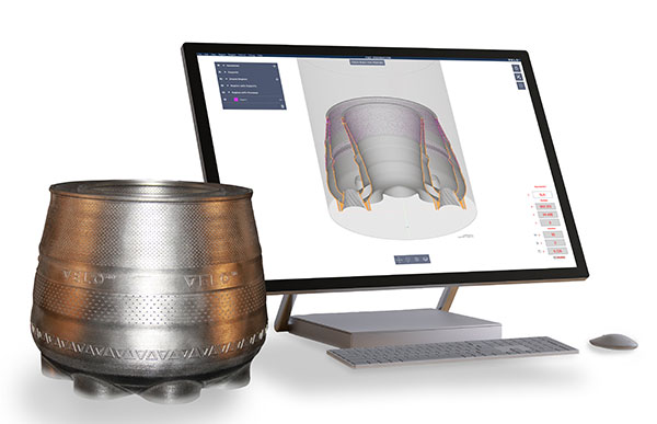
A 3D-printed combustor liner manufactured in Velo3D hardware, shown here with Velo3D’s print-preparation software Flow. Image courtesy of Velo3D.
Latest News
May 2, 2022
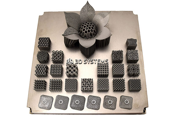
With the ability to create lattice structures, interwoven trusses and micro patterns, additive manufacturing (AM) systems have proven superior to traditional manufacturing in the various shapes and topology they can produce. However, as they rely on 3D models as input, they’re at the mercy of existing modeling software packages—many of which rely on geometry sculpting tools that mimic traditional manufacturing operations.
No matter how advanced a 3D printer is, if users cannot effectively model a print design, they cannot take advantage of the hardware’s full potential. The question today is: Is software shortchanging 3D printing hardware?
According to Brad Rothenberg, CEO of nTopology, “Only if software doesn’t evolve.”
Beyond the Boundary
Most mechanical CAD software packages rely on B-rep (boundary representation) to describe solid geometry, defined by faces, edges and vertices. This format is at the heart of parametric modeling, which allows users to easily edit shapes by changing the boundary values.
Augmented with special surfacing and spline-editing tools, the method works quite well for a wide range of mechanical designs, from a refrigerator’s extruded rectangles with rounded edges to a car’s elegant curves. But the complex shapes and forms 3D printers produce are now beginning to test B-rep’s limits.
Founded in 2015, nTopology started fresh, building its software from the ground up to model topology for AM. But that’s an exception.
“What might be more likely is, you’ll see acquisitions made by some of the larger CAD companies as they start integrating the AM-focused tools,” says Dan Driscoll, manufacturing engineer, Velo3D.
PTC’s acquisition of the generative design software startup Frustum is such an example. Autodesk’s purchase of Netfabb is another. Both led to the integration of AM-specific modeling and simulation tools in PTC and Autodesk’s flagship CAD programs.
“A lot of the parametric CAD software is about describing surfaces. And what people now need to do is to describe volumes more than surfaces,” Driscoll says.
Colton Mehlhoff, applications engineer, Stratasys, is not ready to abandon parametric modeling. AM-optimized topology can be described with a hybrid method, “using parametric and mesh modeling tools,” he says.
Others agree the hybrid approach as the only way to accommodate the dual-format (B-rep + mesh) assemblies engineers will be creating for the foreseeable future.
“It’s common for additive parts to be used in an assembly with parts that are traditionally manufactured,” says Roman Walsh, lead product manager, Ansys. “It’s critical for these parts to be simulated and stored with the rest of the assembly, which means some or most of the model is likely to be created in traditional CAD.”
While meshes are a reliable way to describe organic shapes in low resolution—one reason they’re widely used in character design and animation packages—they present a hurdle in engineering, which demands a higher level of fidelity and accuracy.
For large models with complex lattices, the sheer number of meshes required to depict it could test the memory bandwidth, causing software performance issues. Thus, the quest for a new way to describe lattices is also in progress.
Pixelated, Voxelated, Signed Distance
Not all parametric modeling packages are created equal, says Maoz Barkai, product manager, Oqton. In some cases, the package has evolved so much beyond its origin that the term “parametric” may no longer be accurate.
“Parametric is no longer limited to B-rep and surfaces. In our software, we allow you to do parametric modeling with meshes. You can also use implicit modeling and voxels,” he says. “So you can have a feature tree that holds parametric features that deal with meshes, or deals with other types of geometry that are not solid.”
In simple terms, voxel describes 3D volumes in cubes, adding one more dimension (depth) to the 2D pixels. Many AM hardware makers, such as HP, prefer to use voxel as the nucleus of their print preparation software.
Rothenberg didn’t think voxel was adequate for what he wanted to do. For describing smooth surfaces, he felt it would take too many voxels, leading to heavy computational demand that makes the software unstable or impractical, especially when dealing with complex shapes. So nTopology uses the term signed distance field (SDF).
“If you represent the world with a lot of little boxes, you’re limited by how many boxes you can store on the computer. With our SDF, we’re computing the raw mathematics that gives us a smooth, perfect shape—especially with curves,” he explains.
The Shift to 3MF
As 3D printers get more sophisticated, there’s also a growing desire to find a better alternative than stereolithography (STL). The search led to 3MF, championed and maintained by the 3MF Consortium. With founding members such as Microsoft, HP, Autodesk and Dassault Systèmes adding their weight behind it, 3MF began to take off.
It has AM-specific extensions for beam lattices, materials and properties, slices and other parameters. At the time of this article, 20 companies have joined the consortium, and 27 have adopted the format. These numbers are impressive for an industry with a finite number of players.
But like many newer technologies, 3MF faces the chicken-and-the-egg problem. Vendors will invest R&D efforts to support the superior format if there’s sufficient industry momentum; however, momentum won’t pick up unless vendors begin to adopt and support it.
“As a founding member, Dassault Systèmes is very much involved and driving the format forward. Market adoption of the format will lead to more vendors both on the software and hardware side supporting more of its features,” says Mark Rushton, portfolio senior manager, 3DEXPERIENCE Works, Dassault Systèmes.
Walsh adds, “The best thing about STL is its simplicity and wide adoption. Other than that, STL falls short in what’s needed for 3D printing.”
Similarly, Driscoll notes, “STL has been long outdated. It was just the momentum that kept it in play. Now, we’ve got momentum for 3MF. All the major CAD tools that I know of support it at some level.”
Mehlhoff chimes in, “3MF packs more data than ever into one file. This includes geometry, material, color, texture and even units. It is adaptable to changing technology. It even has room to support variables for specific machines both additive and subtractive.”
But due to the industry’s incomplete support, he cautions, “don’t abandon your other file formats yet.”
Aiming to develop an end-to-end mass manufacturing workflow in metal AM, Velo3D began exploring ways to preserve consistency. It essentially wants to find a way to ensure the same surface finish, resolution and tolerances in parts produced in different machines in different locations.
The key ingredient is printer calibration, according to Will Hasting, director, Solutions Engineering, Velo3D. “Whether you print a part in aluminum or in a nickel-based superalloy, you’ll need to use different laser power and speeds” he says.
Simulating the Print Process
For traditional manufacturing, a slew of CAM programs already exists, but programs for simulating the 3D printing process is another matter. Furthermore, the physical events involved in printing are much more complex.
“Depending on the type of job, an AM build is a very complex problem to solve. You have thermal, phase-change, residual stresses, shrinkage and all kinds of other factors to consider. Even the location on the build plate can mean you have differing results in real life,” explains Rushton.
“In many cases, the engineers in the product development portion of an organization that need to use AM process simulation are not experts in customized FEA; therefore, it is very beneficial to have AM-specific analysis workflows,” says Christopher Robinson, senior product manager, Ansys.
For a while, it seemed AM users would have to figure out how to use the existing finite element analysis (FEA) programs to recreate the morphing, deformation, heat buildup and other phenomena associated with 3D printing. However, the process is getting easier.
Robinson believes standard FEA solvers with customized AM interfaces are an excellent solution.
“When you can tie a traditional FEA tool to the results from an AM-specific analysis tool, then users can really evaluate not only the ideally printed part, but also consider the porosity knockdowns, the actual printed geometry and residual stress to get an even higher fidelity analysis in downstream simulations,” he adds.
A newer breed of AM-specific simulation packages is also emerging from developers such as the WI-based Intact Solutions and Amphyon from Oqton. Intact Solutions is a partner of nTopology. It offers cloud-hosted simulation integrated with the surface modeler Rhino. Currently, it’s developing an offering called Intact. Amphyon is targeted at simulating laser beam melting processes.
Some AM-specific analysis packages are coming directly from the hardware makers, equipped with intimate knowledge of the machine’s strengths and quirks. Oqton, for example, offers 3DXpert, addressing the AM process from design and simulation to print.
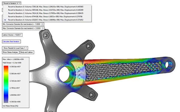
“You can use it to run analysis on lattice structures to see how they respond to stresses, then refine them to be thicker or thinner,” says Oqton’s Barkai.
As the tug of war between AM software and hardware grows intense, the evolution of software picks up speed.
More 3D Systems Coverage
More Ansys Coverage
More Autodesk Coverage
Subscribe to our FREE magazine, FREE email newsletters or both!
Latest News
About the Author
Kenneth Wong is Digital Engineering’s resident blogger and senior editor. Email him at [email protected] or share your thoughts on this article at digitaleng.news/facebook.
Follow DE


