Editor’s Pick: Prototype Electromagnetic Phenomena Virtually

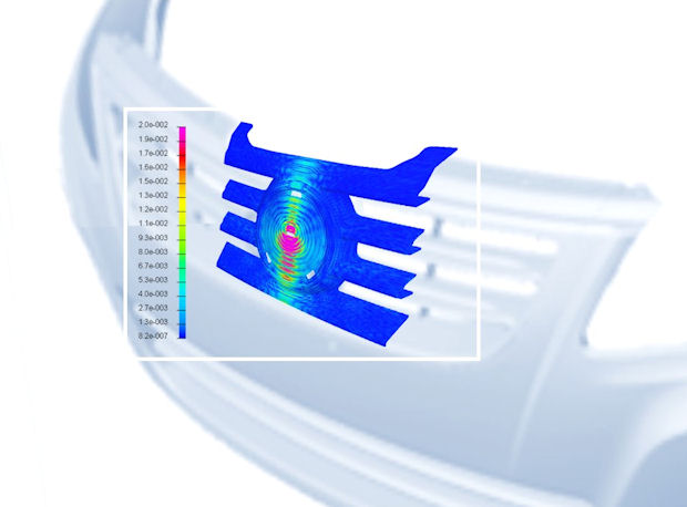
Many of the enhancements in CEM Solutions 2014 focus on automotive applications. This image shows a radar sensor radiating across an automobile’s front plastic grill (induced currents at 77 GHz). Image courtesy of the ESI Group.
Latest News
July 23, 2014
 Dear Desktop Engineering Reader:
 Your car is a mobile data center stuffed with wires, processors, infotainment thingies, sensors galore, communications networks and all sorts of electronics that you see and do not see. It’s also a Faraday cage, assuming it has a metal roof and sides. Even if it’s a convertible, you have a lot of electromagnetic action in there, so you better hope that the people handling electromagnetic compatibility, designing the equipment and integrating the systems have their act together.
Today’s Editor’s Pick of the Week in big part is for the people whose job it is to ensure that electrical interference doesn’t tell the anti-lock brakes to kick in when you hit the wipers. For good measure, it’s also for people working on airplanes, boats, radars and any system crammed with electronics that you’d really prefer work right.
The ESI Group just released the 2014 version of its CEM Solutions integrated electromagnetic virtual prototyping environment. Components in the suite cover diverse applications like EMC/EMI (electromagnetic compatibility/electromagnetic interference) with cable networks, antenna placement and radar signatures.
The CEM in CEM Solutions is an acronym for Computational Electromagnetics. The applications suite, a melding of the company’s PAM-CEM Simulation Suite and Efield Solutions, integrates computational electromagnetics time and frequency methods within a single, multidomain simulation platform. That platform, called Visual-CEM, is actually subpart of ESI’s bigger Visual-Environment, which provides a common platform for multiple simulation domains among its other features. The Visual-CEM platform provides you with the ability to simulate electromagnetic phenomena using coupled and hybrid techniques.
CEM Solutions capabilities of interest to you in automotive and ground transportation industries include enhanced virtual testing capabilities with a dedicated radio noise process. This helps you evaluate spurious electromagnetic noise from internal cabling and emitting components so that you can figure what their noise might do to onboard antennas, receivers and so on.
Version 2014 also introduces a multi-scale modeling process. This process combines computational techniques with analytical formations and the ability to investigate the performance of radar sensors stashed behind plastic bumpers. You can also take into consideration precise design parameters like 3D shapes and surface coating, which means you can assess the effects of thin coats of metallic paint.
Improvements for those of you working on aeronautics, defense and marine applications include updates for radar absorbing materials used in multilayer radome structures and phased array antennas. The functionalities for 3D polar plots have also been updated, which should help with antenna design and scattering studies.
You can learn more about CEM Solutions in today’s Pick of the Week write-up. Scroll down a bit on the CEM Solutions landing page linked at the end of the main write-up. Multiple links there take you to further details on the capabilities of CEM Solutions 2014 that address issues as diverse as conducted and radiated electromagnetic phenomena, multiconductor transmission lines and high-frequency scattering. There’s also an assortment of in-depth technical papers you can download.
Thanks, Pal. — Lockwood
Anthony J. Lockwood
Editor at Large, Desktop Engineering
Read today’s pick of the week write-up.
This is sponsored content. Click here to see how it works.
Subscribe to our FREE magazine, FREE email newsletters or both!
Latest News
About the Author
Anthony J. Lockwood is Digital Engineering’s founding editor. He is now retired. Contact him via [email protected].
Follow DE


