Latest News
August 1, 2012
By Mehrdad Zangeneh
Many turbomachinery manufacturers are facing common commercial drivers such as global competition, price pressure and margin compression, reduced time to market, skill shortages and new developments in manufacturing and materials technology.
The method used for turbomachinery components design has an impact on the extent to which manufacturers can deal with these commercial drivers. Conventional or direct design approaches are typically based on CAD representations of blade geometry—and iterative changes to the geometry using feedback from analysis codes (see Figure 1). These design processes rely on the previous experience of designers, gained over many years, as any changes in geometry can affect the flow at other locations.
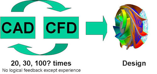 |
| Figure 1: Schematic of conventional design. |
Experienced designers can achieve good performance. But because of the nature of the design process, designers tend to stay within their comfort zones and therefore restrict the design space. This inherent restriction in design space is limiting the ability of designers to meet the commercial drivers affecting the global turbomachinery industry.
An alternative approach for aerodynamic design is the so-called inverse design method in which the 3D blade geometry is computed for a specified distribution of blade loading and pressure distribution (see Figure 2). This approach to design provides more direct control over the design process because 3D pressure distribution on the blade controls all the main flow phenomena, such as secondary flows, shock losses, tip leakage flow, etc. Hence, it removes the need for empiricism and trial-and-error in the design process. It enables designers to use the results from computational fluid dynamics (CFD) more directly to arrive at optimum choices for design specifications, to minimize the effects of particular flow phenomena.
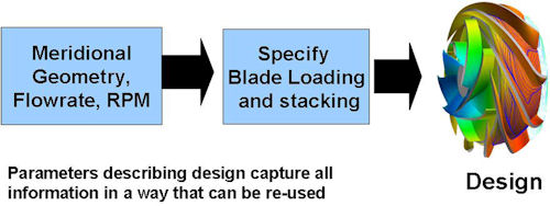 |
| Figure 2: The inverse design process. |
TURBOdesign1, commercialized by Advanced Design Technology (ADT), is an example of a 3D inverse design method that has been applied to a variety of turbomachinery applications. The following examples show how the 3D inverse design approach can not only help designers become more in control of the design process, but can also help turbomachinery manufacturers compete.
Performance Improvements
One of the key challenges turbomachinery manufacturers face is efficiency improvement. This is not only to make their products more competitive, but also to meet the challenges posed by new energy-efficiency legislation in many countries. The application of TURBOdesign1’s 3D inverse design code has resulted in improvements in efficiency over methods in many applications, such as axial turbines, centrifugal or mixed-flow pumps, centrifugal compressors, axial fans and radial-inflow turbines.
In many of these cases, efficiency improvements were possible because the inverse design approach helps to reduce key losses—in the impeller or diffuser for example, in secondary flows or shock losses. In the case of shock losses, the baseline impeller was a turbocharger compressor for a heavy-duty diesel application, the performance of which had not been improved upon via conventional design approaches for more than 10 years. By using the inverse design approach, impeller geometry was designed that showed three-point improvements in performance across the compressor map, based on the test results. In pump and fan applications, typically between three- to five-point improvements in efficiency have been achieved by using the 3D inverse method.
Manufacturing Cost Reduction
Many turbomachinery manufacturers need to reduce manufacturing costs to stay competitive. In many applications, such as pumps or multi-stage compressors, manufacturing costs are directly dependent on volume or size of turbomachinery components. For example, a pump stage was redesigned to achieve a 61% reduction in volume (see Figure 3). The stage’s tip radius had to be reduced substantially to achieve this aim. As a result, in order to achieve the same head, the pump stage loading coefficient (Ψ) had to be almost doubled from 0.33 to 0.6.
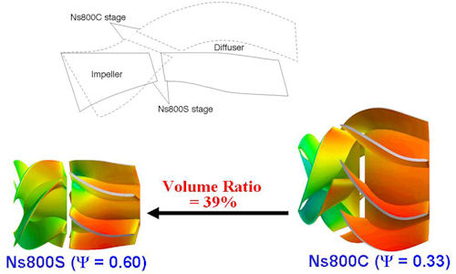 |
| Figure 3: Compact pump stage design. |
Comparing the resulting normalized measured efficiency for the compact stage design with the conventional stage performance showed that the new compact stage performance is similar to that of the original conventional stage, despite having 39% of the volume. The performance of the stage had the same meridional shape as the conventional stage, but redesigned by TURBOdesign-1 it was found to have a peak efficiency 5.8 percentage points higher than the conventional one.
In another application, a radial vaned diffuser was redesigned via the 3D inverse design method to reduce its radial chord by 30% and the number of blades by 25%. Despite the significant reduction in solidity, test data confirmed that the new inverse designed diffuser provides similar pressure recovery as the much larger vaned diffuser it replaced.
Reduced Time to Market
Reduction in development time can have a significant effect on more than just costs. It also provides for important competitive advantages in cases where time to market is important. The 3D inverse design method can result in significant improvements in development time.
For example, consider the development of a new centrifugal compressor stage. In general, there are two main steps in the design process:
1. Cover the points. The design should satisfy the basic duty points — correct pressure ratio, specific work at the design flow rate. Initially, a meanline (1D) design code is run, which provides the basic meridional shape and initial inlet and exit blade angles.
In a conventional design approach, the distribution of blade angle from leading to trailing edges needs to be assumed, and then used together with CFD computations to confirm whether the design produces the correct pressure ratio at the correct flow rate.
By comparison, in the case of 3D inverse design code, all designs produced by input of the relevant design information automatically provide the correct specific work and flow rate, so considerable savings can be made as no CFD iteration is required at this stage of the design process.
2. Optimize the design. Again, the flow-related design parameters in the inverse approach offer advantages in speeding up the optimization of the geometry by allowing designers to explore the design space using their understanding of flow physics.
Multi-objective Optimization
In many applications, providing customized solutions that meet customer requirements—in terms of performance, operating range, cavitation in pumps or noise in fans—can provide competitive advantages. Because of relatively long development times using conventional or direct aerodynamic design approaches, many manufacturers find it difficult to provide customized solutions that are competitive in terms of costs and time to market.
One of the key advantages of inverse design is that the optimum choice of blade loading to minimize particular flow phenomena has generality. For example, in one case, it was shown that the same type of loading distribution could reduce secondary flows in centrifugal compressor and mixed flow pumps. Furthermore, by coupling the 3D inverse design method with automatic optimization strategies, one can develop new knowhow and expertise in terms of optimum loading that satisfies multi-point /multi-objective requirements.
Turbomachinery design based on a direct approach relies on empiricism and long periods of trial and error. To train new engineers in aerodynamic design based on the direct approach can take many months, or even years. Also, it is generally difficult to directly pass the considerable design knowledge of experienced designers to younger staff.
In the 3D inverse design approach, the choice of optimum design specification is less reliant on trial and error, and is based on a knowledge of flow physics. Therefore, it is easier to train new engineers in the design of particular applications.
Mehrdad Zangeneh is professor of thermofluids at University College London, and director of Advanced Design Technology. Send e-mail about this article to [email protected].
More Info
Advanced Design Technology
Subscribe to our FREE magazine, FREE email newsletters or both!
Latest News
About the Author
DE’s editors contribute news and new product announcements to Digital Engineering.
Press releases may be sent to them via [email protected].