
Latest News
October 1, 2011
By James Gordon
Parker Aerospace designs, manufactures and services hydraulic, fuel and pneumatic components, systems and related electronic controls for aerospace and other high-technology markets. Its products include flight control actuation systems and components, thrust-reverser actuation systems, electrohydraulic servo valves, utility hydraulic systems and components, DC motor pumps, fuel pumps, lubrication and scavenge pumps, fuel measurement and management systems, cockpit instrumentation, flight inspection systems, pneumatic subsystems and components, fluid metering delivery and atomization devices, and wheels and brakes.
Parker standardized on Dassault Systemes’ CATIA V5 as part of its journey to becoming a model-based enterprise, replacing 2D drawings with a 3D model as the reference for product definition.
The latest generation of solid modeling systems makes it possible to insert the dimensions, geometric design and tolerancing, annotations and parts lists directly into the solid model, eliminating the need for drawings. The 3D CAD model is now the reference for product definition used by manufacturing and the supply chain, so ensuring its accuracy is more important than ever.
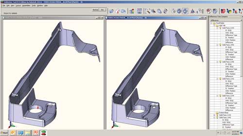
A part in an IS/WAS comparison in Kubotek’s ECO Manager.
In the past, Parker’s engineers defined proposed engineering change orders (ECOs) by redlining either a paper drawing or a CAD file. The redlined drawing or file was then sent to those responsible for reviewing the change for their approval. After the change was approved, the engineer had to start all over again by actually changing the CAD file. After the change was made, it had to be carefully checked to ensure that the changes were accurately made and that nothing else in the file had accidentally been changed. This process took a considerable amount of time.
Streamlining the Process
Bob Deragisch, Parker’s engineering services manager, had the idea of improving the ECO process. He decided the capabilities of the Kubotek ECO Manager software package could make it happen.
“A key advantage of ECO Manager is that, rather than comparing random points, it compares the mathematical geometry definitions to completely catalog the differences between the source and target files,” Deragisch says.
ECO Manager uses Kubotek’s pattern-matching technology to compare two revisions of product data to identify all differences between the data sets. It supports most native CAD formats, and works directly with the native CAD file to eliminate data translations. It compares both the 3D geometry and the model-based design information, such as tolerances and marking, to ensure all revisions are identified—ensuring that the impact of every change is fully understood.
Once the revisions have been identified and organized, ECO Manager provides several reporting options. It stores the data model that defines the differences between the files in electronic format, and can generate customizable graphical change reports in PowerPoint or PDF format.
Now, Parker uses ECO Manager to compare the old and new CAD files, and generate a report that identifies and organizes the differences. This report becomes a key part of the ECO approval package that is sent to reviewers. After the change is approved, nothing else needs to be done except processing the change request through the product lifecycle management (PLM) system so that the new version of the CAD file is released as the product definition master.
There is no need to make the change a second time, as was required in the past. Nor is there a need to manually check that the change has been made correctly or that nothing else in the document has been changed, because ECO Manager has identified every change in the new CAD file as part of the approval package. This new process is saving substantial amounts of time on every ECO, Deragisch says. It also avoids the possibility of costly communications mistakes by ensuring that the change that is made to the product exactly matches what the reviewers approved.
Validating the CAD Translation Process
Parker provides parts for nearly every airplane in use today—and many of these airplanes have been flying for several decades. As a result, the company’s move to CATIA V5 created the need to translate hundreds of thousands of older CAD files to its new CAD standard. The company found automated translation solutions for each of its CAD programs, but recognized that it would take an enormous amount of time to manually compare the CAD files.
“We knew from the beginning that differences in the geometric kernels between the previous programs and CATIA V5 would cause differences between the old and new files,” Deragisch says. “In most cases, these differences would be very small. If the differences are smaller than our manufacturing tolerances, then it’s not a problem. If they are larger, then we need to correct the translated file.”
ECO Manager produces a report on each file that can be configured to segregate differences that are larger or smaller than a specified tolerance level. This feature was particularly valuable to Parker because the tolerance levels at which the files need to be compared are different for different parts.
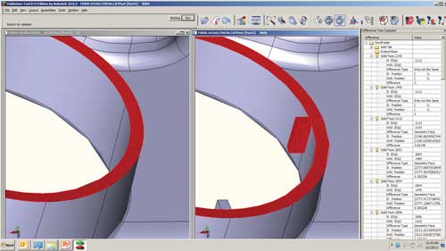
The identification of a difference, both highlighted on the model and in the difference tree.
“We considered doing a manual comparison, but when we estimated the time required to compare the files for just one of our smaller divisions, it turned out to be a 27 ‘person-year’ effort,” Deragisch says. “We looked at several tools that created a point cloud on the surface of the source file, and compared them to a similar point cloud created on the surface of the target file. The problem with these tools is that they only compared a sampling of points, so there was no way to be certain that the tool had found all of the differences between the two files.”
The Parker team configured ECO Manager to automatically compare a large number of source and target CAD files. For each comparison, the team set a first tolerance level that is small enough to definitely be within manufacturing tolerances and does not require modification. A second, higher tolerance level was defined so that differences above the first level but below the second level may be checked manually to see whether changes are needed. Finally, a third, even higher tolerance level was set for differences at or above this level that definitely require modification of the target file.
| Taking a Deeper Look This article and the following one on page 26 are part of a series that looks at one company’s engineering practices. Last month, the articles in the “DE on the Case” series explained how Parker Aerospace created a virtual workstation cluster to speed its simulation jobs. DE also produced a white paper on workstation cluster computing, which was sponsored by Intel and HP. It can be downloaded for free. |
After performing the comparison, ECO Manager generates a report that includes a model with all of the differences between the source and target files highlighted and color-coded. Differences that were highlighted in green did not need to be checked. Differences highlighted in yellow needed to be checked manually to determine whether changes were needed. Finally, differences highlighted in red were manually corrected in the target file to match the source file.
Looking Ahead
Parker Aerospace has identified yet another application that it plans to implement in the future. The length of time over which aerospace programs exist means that they inevitably have to be moved from release to release of the CAD package used to develop them.
“We need to be sure that when we move to a new release that the geometry of our existing programs has not changed,” Deragisch says. “It would require a huge amount of time to make this determination manually, but with ECO Manager, it is a simple, automated process. We also have a number of customers, particularly in the propulsion side of the business, that do not use CATIA as their standard. For these customers, we will design parts in CATIA and then translate and deliver a 3D model in the format of the CAD package used by our customer. ECO Manager will be used to demonstrate that the models are geometrically equivalent and will save time by automating this comparison.”
Deragisch estimates that ECO Manager has saved “hundreds of years of effort” through its ability to accurately and completely compare CAD files and catalog the differences.
“We have achieved substantial time savings in the ECO process by highlighting the differences between the existing product definition and the proposed changes, while ensuring that nothing else has been accidentally changed,” he concludes. “In addition, this new approach provides an independent validation of the translation process, which helps to ensure the accuracy of our critical product definition files.”
This month, we focus on how Parker Aerospace manages engineering change orders and show you an example of how Parker Hannifin’s Engineered Polymer Systems division uses non-linear FEA to improve product design. If your company would like to be the subject of a “DE On the Case” story, email us at [email protected].
James Gordon is vice president of Development for the ECO Manager product line at Kubotek USA. Prior to his work at Kubotek, he was vice president of Development and Chief Architect of ACIS, a product of DS Spatial Corp.
For More Info
Subscribe to our FREE magazine, FREE email newsletters or both!
Latest News
About the Author
DE’s editors contribute news and new product announcements to Digital Engineering.
Press releases may be sent to them via [email protected].