Latest News
August 1, 2004
By Louise Elliott
As interest in the information provided by CFD has grown recently, some developers have made the most frequently used capabilities of the technology easier for design engineers to use by embedding or closely relating them to popular CAD programs.
“CAE has been an elite subject, with complex tools that were easy to forget dedicated to their use,” says Dr. Ashok Das, manager of the Center for Modeling and Simulation at Applied Materials, Santa Clara, CA, manufacturers of semiconductor wafer processing equipment. “Nowadays, not many companies can afford many dedicated analysts. My vision is to bring CFD and FEA tools to the desk of design and process engineers.”
Das, who has used high-end CFD and FEA tools himself, is driving software suppliers to develop CAD-integrated CAE tools that his design engineers can use. Such software would also help analysts cut down their preprocessing time and improve productivity.
His team uses CFD-CADalyzer from ESI Group, which works with most popular CAD programs.
“It’s important to us to analyze flow through conceptual designs of valves to make sure no major restrictions hamper the flow,” says Peter White, project engineer for the Fluid Control Division of Parker Hannifin, New Britain, CT. White uses CFDesign from Blue Ridge Numerics, Inc. (BRNI), with Autodesk Inventor primarily to study compressible and incompressible flows.
“CFD is, in general, complex,” he says, “but CFDesign makes it relatively easy to use for someone with little previous experience. If it’s used in the early stages of design it has the great benefits in terms of improved product quality.”
Owen Warr, project engineer with Zero Zone, Inc., North Prairie, WI, makers of display coolers, freezers, and refrigerated merchandising cases, has had more than 15 years of experience using a variety of CAE tools. “When it comes to CFD, I remember when I had to write my own programs in Fortran, get geometry from 2D AutoCAD, then merge the program and geometry into Abaqus to run CFD. The dramatic changes in CFD since then are almost surreal,” he says.
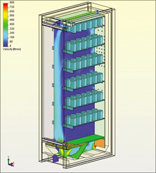
Warr uses SolidWorks and COSMOSFloWorks from SolidWorks to study air flow design in cooler and freezer cabinets (below). “I can run close to a million equations in 24 hours with this software, on full and/or partial fluid cells, depending on the geometry, and on a very ordinary PC platform.”
All three of these CAD-based CFD programs position themselves in the same way FEA did with design analysis in the mid-1990s—as tools meant to be used as early in the design process as possible, and thus, “as an extension of the design systems themselves,” says Ed Williams, president of BRNI.
But each one is a bit different from the others. CFDesign, the first out of the gate, and currently the market leader, works in partnership with many of the leading CAD programs to provide direct access through its application programming interfaces (APIs). CFD-CADalyzer, the most recent offering, does what product manager Mike Nieburg calls “real-time read of native kernels” through Simmetrix (Clifton Park, NY; simmetrix.com), a well-known supplier of techniques, tools, and libraries for simulation, which contains the Parasolid, ACIS, and Granite kernels. COSMOSFloWorks is embedded in SolidWorks, and works only with that CAD program, to “perform goal-based fluid analysis,” says Suchit Jain, vice president of Analysis Products for SolidWorks.
All three programs were developed to perform basic flow analysis—laminar and turbulent, as well as heat transfer and in some cases, radiation. They do not compete seriously for the dedicated analyst market, which needs the complex physics and fluid models available at the high end of CFD. However, some dedicated analysts who have access to both sets of products are delighted to use CAD-based CFD to set up their problems.
Vadim Uchitel, software technical manager for the ESI Group, points out that less than 5 percent of engineers use CFD, and those who do use it, do so less than 10 percent of the time. To be able to be used on such a part-time basis, the software has to be easy to use, easy to learn, and easy to remember. All three systems succeed very well in that arena—to the point where the high-end CFD vendors are currently trying to copy at least part of that ease of use (for more on this topic, see the roundtable discussion in June’s Elements of Analysis supplement).
Overcoming Challenges Early and OftenWarr of Zero Zone says that he has created his own CFD models using SolidWorks. “Users with experience can do much of what analysts do with more complex programs,” he says. “However, doing so requires obtaining a good deal of information and thoroughness. For example, to analyze airflow in a cabinet where the flow is driven by a fan, it’s best if the engineer doesn’t select the fan just by the number of cubic feet of air it will produce for a given space, but rather gets the manufacturer to provide the fan curve. If he enters that data into COSMOSFloWorks, the result will be quite accurate.”
Patrick Truitt, senior mechanical engineer with Respironics, Murrysville, PA, a company that makes ventilators and a home device for sleep apnea, uses CFDesign with Pro/Engineer to analyze pressure generated by the sleep apnea machine. “The device uses a fan to produce positive pressure, so that when the user falls asleep, his or her throat doesn’t close. CFDesign models the fan blades and the pressure drop created by the inlet muffler. It’s a 20,000 rpm fan—so it’s a challenge to make it as quiet as possible for bedside use,” he says.
“The biggest challenge in moving from CAD to CFD is getting the reverse geometry for seeing the spaces through which the flow passes. CFDesign is working on making that automatic,” says Truitt, adding that some parts that are not essential for flow analysis need to be suppressed, so that the CFD model can be meshed. “We use CFDesign after we complete the design, but before we order tooling. It’s the very early prototype stage. We order rapid prototypes to confirm the design—and the results of CFD come very close to those of testing.”
GElcore, Valley View, OH is a joint venture of GE Lighting and semiconductor manufacturer Emcore, which makes high brightness LEDs, and is working on producing white light for general illumination purposes. James Petroski, Package Design and Analysis engineer, says that although LEDs are low-power devices, in large numbers they can produce a great deal of heat. “We use CFD-CADalyzer as an extension to thermal analysis, because to make LEDs last, they have to be run cool enough to avoid their top power range where they burn out fast. I also use it in other devices where air circulation is important.”
Petroski likes the fact that CFD-CADalyzer can be used in conjunction with CFD-ACE from CFD Research Corp., and he says that ESI worked with him to meet his specific needs. “I find the interface very logical and easy to use. It looks a lot like my regular FEA program’s interface, so it’s easy to get back to after not using it for a while.”
Larry Miller, an engineer with pump manufacturer Quizix, Inc., North Highlands, CA, finds that the close relationship between COSMOSFloWorks and SolidWorks makes it easy for him to study the flow path of fluids flowing through a valve. “It’s very easy to see the flow path, because SolidWorks can extrude materials or cut parts away. The biggest benefit is that we already have the parts modeled—saving time compared to creating it again in an analysis program. I’m a new engineer, COSMOSFloWorks is my first analysis tool, and I became comfortable with it quickly.”
That comment underscores the attractiveness of CAD-based CFD programs for design engineers. The programs make it simpler to learn, use, and trust than anyone could have imagined a few years ago when it belonged only to scientists and dedicated analysts.
Contributing editor Louise Elliott is a freelance writer based in California. Offer Louise your feedback on this article through Desktop Engineering Feedback.


