
The PCB and electrical add-ons integrate PCB design and wiring with Solid Edge models. Changes made in one environment automatically update in the other. Images courtesy of Siemens PLM Software.


Latest News
October 1, 2018
Siemens PLM Software recently released the latest updates to Solid Edge, its mainstream engineering and design software aimed at small and medium-sized businesses. Solid Edge 2019 represents a broad expansion of the company’s product development software portfolio, thanks to newly integrated capabilities, many the result of recent corporate acquisitions.
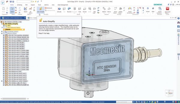 Solid Edge 2019 retains its clean, intuitive interface. A new auto-simplify tool can reduce parts to a geometric lump representing their external shape. Images courtesy of Siemens PLM Software.
In particular, the new release integrates electrical tools for wiring, harness and printed circuit board (PCB) design. Solid Edge 2019 also incorporates improvements in additive and subtractive manufacturing, and modular plant design, and includes access to the Solid Edge Portal, a secure online service providing CAD management, viewing and collaboration capabilities for controlled project documentation and CAD file sharing.
Solid Edge 2019 (also referred to as ST10) is the program’s 30th release. Originally developed and released by Intergraph in 1996 using the ACIS geometric modeling kernel, the software was purchased by UGS in 1998, at which time the modeling kernel was switched to Parasolid. In 2007, UGS was acquired by the Automation and Drives Division of Siemens AG and the company name was changed to Siemens PLM Software.
A Well-designed Interface
Solid Edge offers a clean interface. When you first install the software, you can select an interface theme, which essentially determines how much assistance the software provides as you use various commands. You can change this at any time from the Quick Access Toolbar.
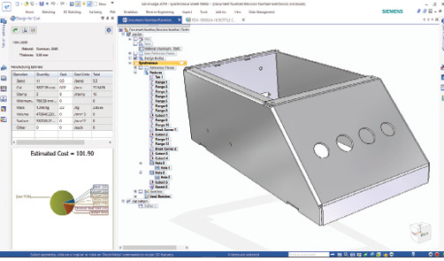 A new sheet metal enhancement updates the estimated cost of a part in real time as you make changes to the model.
The basic user interface consists of an Application menu and Quick Access toolbar. Below this, a ribbon extends across the screen and organizes commands into tabs and panels. Along the left side, a scrollable window called the PromptBar displays prompts and messages related to the current command while the PathFinder organizes all the active document elements into a hierarchical view. When working in the part environment, this shows the feature tree, while in the assembly environment, PathFinder displays the components making up the assembly. A tabbed document interface fills most of the screen, with a Command Finder and view control tools along the bottom edge. There is also a Quick View cube in the lower-right corner of the document window that you can use to quickly reorient the model.
You can begin an ordered model by creating a two-dimensional (2D) sketch and then adding features (lofts, revolves, sweeps and more) as you would when using a typical solid modeler, with each step recorded in the feature tree. You can use shape handles to manipulate the model, use a steering wheel to create and edit geometry, or press and drag the right mouse button to display a radial menu where you can select various tools. The cursor’s appearance changes as you use various commands and some commands also bring up a command bar, which displays command options and data entry fields for the command in progress.
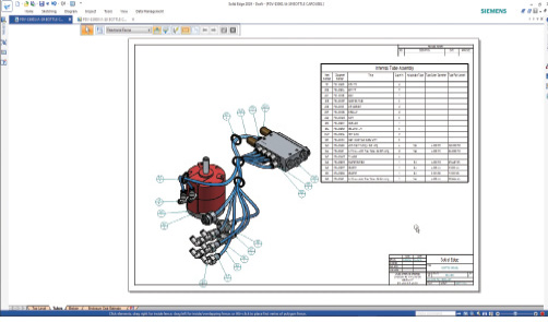 Improvements to tube design include a new route command. Resulting drawings include an accurate bill of materials.
You also can use direct modeling to modify geometry without regard to existing—or in the case of imported models, the lack of—parametric data. Direct modeling changes made to an ordered model are appended to the feature tree, just like any other ordered feature.
But Solid Edge also combines direct modeling with dimension-driven design—Siemens calls this Synchronous Technology (ST)—enabling parametric features to be applied directly to solid features without having to rely on 2D sketch geometry. When preparing to make synchronous edits, tools in the Design Intent panel help preserve or alter the design intent. For example, when selecting and dragging the face of a symmetric part, toggle off the symmetric design intent to alter just that face.
Improvements to Core Tools
Solid Edge 2019 introduces some exciting new features. For example, you can automatically simplify assemblies to speed the design process and protect intellectual property. Auto-simplify results in a part or assembly being converted into a solid geometric lump that represents the part or assembly’s external shape. Within the assembly, you can then easily switch to and from the simplified representation.
Solid Edge 2019 can also calculate the volume of any enclosed container based on an intersecting plane, such as the surface of liquid in a container. A goal seek function can then find the surface level based on a given volume.
Solid Edge has long had some of the best sheet metal tools. Solid Edge 2019 now enables users to estimate the manufacturing and material cost of a sheet metal part in real time. Cost estimate data comes from Siemens’ suppliers as well as information you supply. As you make choices and adds bends, cuts, stamps and so on, there is immediate feedback on how decisions will likely influence the cost, and one can automatically generate cost estimate reports.
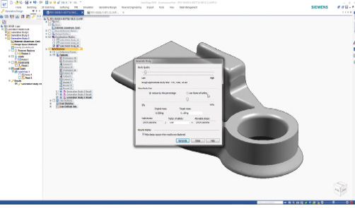 You can now apply multiple loads in a single generative design study and create optimized designs that can be manufactured using standard machining.
Solid Edge 2019 brings enhancements to tube design, allowing the placement of the same tube subassembly multiple times using different paths. A new Route command lets one quickly adjust the tube path so that it passes through specific fittings or clips, yet parts lists continue to show the correct number of occurrences of each tube even though they have physically different paths.
New for generative design is the ability to apply multiple load cases within the same study, so that opposing forces can be used to optimize the design. New controls allow for changing the distribution of material, while other enhancements allow the creation of an optimized design that can still be manufactured using regular subtractive machining. Parts can also be optimized to meet a given factor of safety. In addition, when working with mesh data, Solid Edge can now recognize planar and cylindrical faces, enabling users to add features and create assembly relationships.
Lastly, views can now be broken at any angle beyond just horizontal or vertical, further enhancing the creation of 2D production-ready drawings. And improvements have been made to the KeyShot renderer.
Lots of Add-ons
In addition to the new features and functions in Solid Edge itself, Siemens also announced multiple add-ons for electrical design, simulation, manufacturing, technical documentation and data management.
For example, Solid Edge adds new tools for wiring, harness design and electrical routing. Solid Edge Wiring Design provides design simulation tools for the rapid creation of wiring diagrams and verification of electrical systems. The harness design tools allow for the creation of nonscaled and full-size form board designs. Electric circuits can be analyzed and validated. Qualitative analysis gives the ability to check a circuit’s correctness, while numerical analysis can be used to indicate dynamically any voltage drop or load issues.
Users can run the wiring and 3D modeling environments in cross-connected mode (even across a network), so that physical changes made to the 3D model, such as wire lengths, are reflected in the harness design. When selecting a wire, harness or connector in one environment, it highlights in the other, and any changes made in either environment transfer across.
Solid Edge PCB Design enables designers to create 2D and three-dimensional (3D) views of printed circuit boards (PCB) and related components. After creating a PCB outline and determining the location of mounting holes in Solid Edge, the data can be imported into PCB Design for initial placement of components with fixed locations, such as connectors and taller components that may cause conflicts. Engineers can then complete the electrical design of the PCB. A collaboration file is then created and read back into Solid Edge, creating an associative link, so that changes made in either Solid Edge or the add-on are automatically reflected.
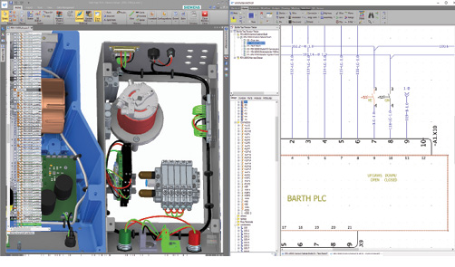 The PCB and electrical add-ons integrate PCB design and wiring with Solid Edge models. Changes made in one environment automatically update in the other.
The Structural, Thermal and Flow Simulation add-on expands upon the program’s structural and flow simulation capabilities. In addition to static studies for stress, strain, buckling, vibration and steady-state heat transfer, you can now study the effects of heat moving through parts over time, also known as transient heat transfer. This allows designers to see temperature changes over time to assess things like heating and cooling performance. Flow simulation also can be used to analyze the behavior of fluid moving, sloshing and flowing within a container.
Solid Edge 2019 adds an entirely new add-on for plant design. Solid Edge P&ID Design provides 2D flow diagram and symbol support for creation of P&ID drawings with support for ANSI/ISA (American National Standards Institute/Industry Standard Architecture), DIN (Deutsches Institut für Normung e.V., which stands for German Institute for Standardization) and EN ISO (International Standards Organization) standards. Solid Edge Piping Design then provides automated 3D piping design with comprehensive 3D part libraries and fully automated isometric drawing output for plant design.
Solid Edge CAM Pro (previously called CAM Express) provides a computer numerically controlled programming interface that maintains associativity with the Solid Edge 3D model. The latest version handles product and manufacturing information with feature-based tolerance data.
There are also new add-ons for Requirements Management, which provide role and credential-based authentication and allow users to track key design tasks and improvements to the Solid Edge Technical Publication add-on, which provides an integration between Solid Edge and QuadriSpace’s technical documentation software.
Finally, rounding things out, Siemens offers data management tools and cloud collaboration capabilities, including improvements to the integration between Solid Edge and Siemens’ Teamcenter PLM system. An interesting final piece is the browser-based Solid Edge Portal, which allows users to view, share and mark up CAD files from any device. The portal also includes explode and sectioning tools, and Solid Edge users get 5GB of space on the portal for free.
Pick Your Level
Solid Edge is available in four levels. Solid Edge Design and Drafting provides 2D drafting, basic 3D part and assembly design, automated 2D drawings, synchronous technology (intelligent direct modeling) and design automation. This entry-level also includes a standard parts library, animation, mesh data import and basic motion simulation.
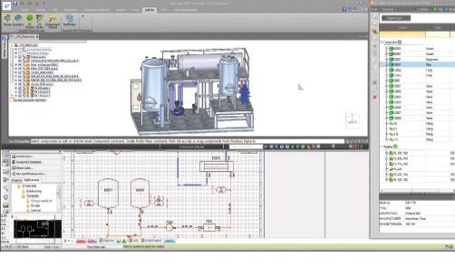 Solid Edge P&ID and Piping Design facilitate the creation of flow diagrams and fully automated isometric plant drawings.
Solid Edge Foundation provides more complete 3D part and assembly design and adds sheet metal design, frame and weldment design, surface modeling, plastic part design, jig and fixture design and conceptual assembly layout. It also includes data migration for SOLIDWORKS, Inventor and Pro/E and Creo, as well as more complete motion simulation.
Solid Edge Classic adds CAM, gear, pulley, shaft, spring, beam and column design, extensions to the parts library, 3D scanning, generative design, photorealistic rendering, and basic stress and vibration simulation.
Finally, Solid Edge Premium incorporates everything in the lower cost packages and adds wire harness design, piping and tubing design, more complete stress and vibration simulation, and buckling simulation, thermal simulation and optimization.
You can download a free 45-day trial or stream the trial on a web browser, thus avoiding having to download any files. With all its improved core features, plus multiple add-ons, Solid Edge 2019 is a pretty significant release.
For More Info
Solid Edge 2019
Pricing
- Solid Edge Design and Drafting: $100/month or $900/year
– or perpetual license:* $2,117 (+$476/year maintenance)
Solid Edge Foundation: $230/month or $2,220/year
– or perpetual license:* $4,239 (+$1,375/year maintenance)
Solid Edge Classic: $290/month or $2,760/year
– or perpetual license:* $5,830 (+$1,591/year maintenance)
Solid Edge Premium: $420/month or $3,940/year
– or perpetual license:* 8,376 (+$2,262/year maintenance)
* Price is for a node-locked license. A floating license is slightly higher.
System Requirements
- OS: Windows 10 Enterprise or Professional (64-bit only) version 1709 or later; software can be installed on Windows 8.1 Pro or Enterprise (64-bit only) or Windows 7 Enterprise, Ultimate, or Professional (64-bit only) with Service Pack 1
- Memory: 4GB minimum, 8GB or more recommended
- Disk Space: 6.5GB required for installation
- Display: 65K color minimum (TrueColor recommended; 1280x1024 or higher resolution
Subscribe to our FREE magazine, FREE email newsletters or both!
Latest News
About the Author
David Cohn is a consultant and technical writer based in Bellingham, WA, and has been benchmarking PCs since 1984. He is a Contributing Editor to Digital Engineering, the former senior content manager at 4D Technologies, and the author of more than a dozen books. Email at [email protected] or visit his website at www.dscohn.com.
Follow DE

