Predicting Structural Instability Due to Plastic Hinge Collapse Mechanism
Using simulation to understand structure collapses due to plastic hinge effects.
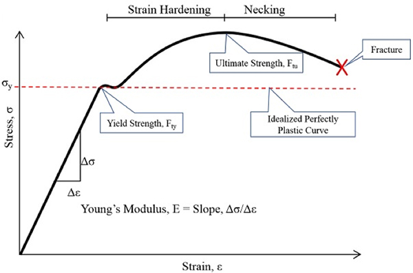
Fig. 1: Typical stress-strain curve for mild steel. Image courtesy of David R. Dearth/Applied Analysis & Technology.


Latest News
July 19, 2019
When engineers are asked to evaluate a part of assembly for structural capability, there is always some criteria specified to bound the investigation. Some of these criteria are to ensure that specified limits of stress or deflections are not exceeded. Design of structures based on conditions where loading results in full plastic yielding creating structural instability where the structure collapses due to plastic hinge effects is increasingly used and accepted by various codes of practice, particularly for steel construction. Fig. 1 shows a typical stress-strain curve for mild steel and the idealized plasticity curve for performing plastic analysis.
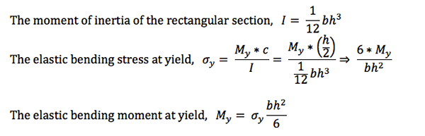
Plastic hinge effects are defined as the moment at which the entire cross-section has reached its yield stress. This is theoretically the maximum bending moment that a cross-section can resist. When this point is reached a plastic hinge is developed and the structure becomes an unstable mechanism.
A fully comprehensive discussion of plasticity effects far too lengthy for a magazine article. However, one can gain a great deal of insight into the process by considering a simple example.
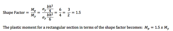
Review: Plastic Moment of a Rectangular Section
Consider a rectangular cross-section under the action of positive bending moment, which has developed into a plastic hinge (see compression/tension image below). The distribution of bending stress remains linear up until the point where peak fiber stresses exceed the yield point. Plastic yielding takes place until the entire cross-section yields. The plasticity assumption for a rectangular section is that the upper half of the rectangular section experiences fully plastic yielding in compression and the lower half experiences fully plastic yielding in tension. Yielding in compression is assumed equal to yielding in tension.

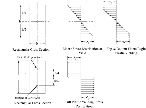
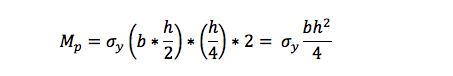
When bending moments continue to increase and yielding exists across the full cross section, the plastic bending moment, Mp, is computed by summing moments about the plastic neutral axis. With the assumption that the yield stress in tension = yield stress in compression.
A “shape factor” can be defined that is the ratio of the plastic moment / elastic moment at yield. The shape factor for a rectangular cross section becomes the following:
Sample Problem: Plastic Bending of Simply Supported Beam
A great deal of insight into the process of analyzing plastic hinge effects can be gained by considering a simplified example problem. Fig. 2 shows a simply supported beam subjected to a uniform loading, w lbs./inch. It is desired to determine the maximum loading that will produce a plastic hinge and cause the beam deflections to become unstable. To gain confidence in our solution we will present two approaches: (a) hand solutions using conventional equations found in most engineering textbooks on plastic hinges and (b) correlate results with a finite element idealization.
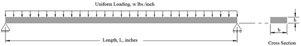
Fig. 2: Simply supported beam subjected to uniform pressure.
Answers: Step 1: Hand Analysis of Plastic Hinge
Let the beam cross-sectional dimensions, b = 1.0” and h = 0.5”, length of beam L = 12”, and let the uniform loading be represented by a uniform pressure, Polbs./in2. Using conventional hand equations found in the engineering literature, the maximum bending moment for a simply supported beam with uniform loading is the following:
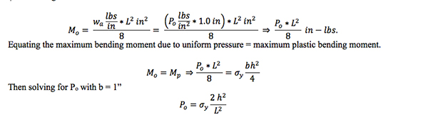
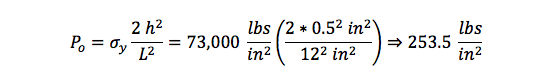
Where Po represents the collapse pressure due to the fully plastic hinge effects. Assume the material is mild steel with Young’s modulus, E = 29 x 106 psi and material yielding is perfectly plastic at stress Fty= σy= 73,000 psi. Substituting into the above equation and solving for the collapse pressure, Po …
Answers: Step 2: Nonlinear Transient Finite Element Analysis
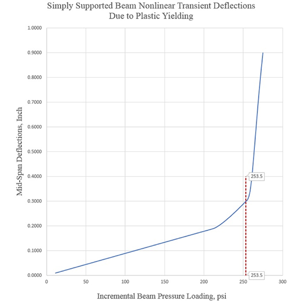
Next let’s see how this problem can be solved using a finite element analysis (FEA) simulation model. Fig. 3shows a FEA simulation model of the simply supported beam with uniform pressure loading. To ensure the collapse pressure load isn’t missed, the pressure loading is defined at 275 lbs./in2. The analysis settings are for a nonlinear, static, transient solution. The process is to monitor the deflections at the mid-span of the beam and when a plot of the deflections becomes unstable, i.e., large increase in deflections with a very small increase in loading magnitude that will define the collapsing pressure due to plastic hinge effects.

Fig. 4 plots results of the nonlinear, static, transient results for incremental pressure loading vs. the beam mid-span deflections. From Fig. 4, deflections versus loading remain linear until yielding of the cross-section begins to take place. The material yielding causes the slope of the deflection vs. load curve to increase. When full plastic yielding takes place, the slope of the deflection vs. load curve becomes very steep. Unstable deflections exist when a small incremental increase in loading results in a large change in deflections.
Applied Analysis & Technology was founded in 1982 and has design and analysis experience in mechanical engineering, aerospace, computer peripherals, medical components, piping networks, other high-tech related fields, custom software, test equipment and prototype development. The customer base extends throughout the U.S. and as well as Europe and South America. The consulting firm focuses on finite element analysis and computer-aided design. Applied Analysis & Technology uses specialized consultants in traditional design, metallurgy, failure analysis, conventional mechanical analyses and environmental testing and other disciplines to achieve the desired technical evaluation or design.
David R. Dearth is president of Applied Analysis & Technology, Huntington Beach, CA and can be contacted by e-mail at [email protected]. Visit the website at AppliedAnalysisAndTech.com.
Subscribe to our FREE magazine, FREE email newsletters or both!
Latest News


