

September 1, 2019
Editor’s Note: Tony Abbey provides live e-Learning courses, FEA consulting and mentoring. Contact [email protected] for details, or visit his website.
This article reviews the Paramatters CogniCAD Topology Optimization and Generative Design program from Paramatters. CogniCAD is a cloud-based application. The user uploads CAD geometry to define design space in STEP file format. The emphasis with CogniCAD optimization is that the resulting smooth geometry is directly suitable for export and use in additive manufacturing as an STL or STEP file. CogniCAD also includes stress constraints to help ensure the resultant structure has viable strength.
The design study carried out for this walkthrough develops a support structure for a container and its contents, connected to the ground at four attachment points. The container and its contents are subject to two inertia load cases: vertical and lateral.
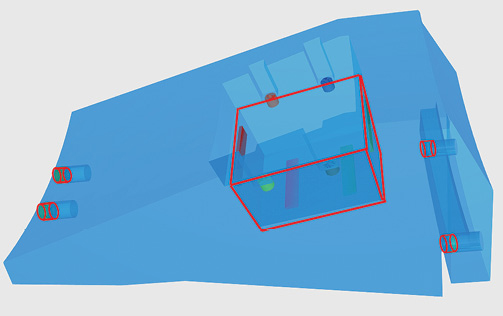
Fig. 1 shows the design scenario, as displayed in CogniCAD. I have outlined the support bolts and the container to emphasize the design intent.
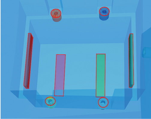
The blue geometry is the allowable design space, within which material can be added or removed by the Topology Optimizer. The container occupies the empty volume within the design space. Additional empty volume is defined for access to bolts during assembly. The four support bolts are defined as non-design space. The material in these regions is preserved. Further non-design space is defined around the container region; four attachment bolts and four support pads. This is shown highlighted in Fig. 2.
The single design space and multiple non-design spaces are defined by parts in an external CAD assembly and then imported into CogniCAD as a STEP file, with dimensions in mm. Fig. 3 shows the CogniCAD interface with the assembly imported. All parts are listed in the left-hand panel with design or non-design space status undefined by default.
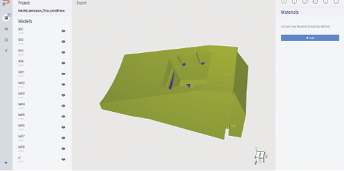
Fig. 3 shows a sequence of steps from 1 to 6 in the right-hand panel. The first step, to add material properties, is shown pending. In this case a single material property, titanium TiAl6V4, is selected from the CogniCAD material library. The user can then proceed to step two—defining design and non-design space using the assembly parts. Of note is that non-design space is contained within design space, rather than abutting design space.
There is only one part defining design space, so the other 12 parts remain undefined in this step. Step three is to define these (the bolts and pads described earlier) as non-design space.
Step four defines the load cases, with their loading and constraint actions. The user has the option to define these manually, or to be guided by the CogniCAD AI tool. I am using the manual method here. For each load case the sequence is to define the load case name and analysis type, define the constrained parts and define the parts where loading is applied. Fig. 4 shows the loading defined as a group, applied to multiple parts. CogniCAD calculates the combined c.g. of the parts and then forces and moments can be applied through this point. Fig. 4 shows the user interface with constraints selected and a group load ready to be defined.
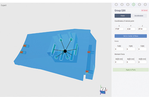
The c.g. can be used as the loading point, or any user-defined point. In this case accelerations are being used, so the acceleration tab is selected instead. This requires the definition of the non-structural mass of the group. This represents the payload of the container and its contents. In this case the value is 0.44 kg, distributed to the parts. This value can be edited for each part to give a more sophisticated breakdown. The value of acceleration (400 g) and direction ( -y) is also defined.
The load case is saved, and another load case can optionally be created. The setup is repeated with the same mass and acceleration value, but this time in the (-z) direction. Conveniently, the constraints can be directly copied from the previous load case. The loaded parts can be highlighted for each load case as a check.
We can now move on to step five where the optimization controls are defined. There are two options here:
- Generative Design Exploration
Described as maximization of design stiffness to specified fraction of material, this is the traditional topology optimization approach. It requires an estimate of the volume fraction and does not attempt to meet stress or displacement constraints. It is simpler technology and is less CPU intensive and hence cheaper and faster than the alternative option, which applies response constraints.
- Lightweighted Generative Design for Engineering Applications
This is described as minimization of mass subjected to stress, deformation and vibration constraints. The version I have used is limited to stress constraints, but other constraints will be available in an upcoming release. In this case the volume fraction is automatically adjusted to get the most efficient design.
Paramatters emphasizes the power of its response constraint method to achieve practical designs quickly. The volume fraction method is useful as a complementary design space exploration tool. In this study I will use the volume fraction constraint and then the stress constraint method.
Generative Design Exploration Runs
The objective is to minimize compliance (maximize stiffness) subject to the volume fraction constraint. Each load case can be individually weighted. For example, the vertical load case could be considered more important than the lateral load case. This is probably more useful in exploring design trends, rather than meeting formal loading envelopes. I have set the weighting to be equal and the volume fraction at 30%—meaning 70% of design space will be removed.
At this point CogniCAD estimates the solution cost in tokens. Two additional parameters that affect cost are solution speed (slow, medium, fast) and resolution (low, medium, high). Resolution will also directly affect the fidelity of the solution and hence minimum member size. My initial run used medium resolution as I was anticipating a slender configuration, rather than a chunky monolithic configuration. I also used fast solution time (medium speed is not available with medium fidelity).
Two other design options are available: selecting between an additive manufacturing or investment casting manufacturing process, and in the case of additive manufacturing, controlling the overhang angle. I used additive manufacturing with a default overhang of 45 degrees. This attempts to promote arch-like supports for flat regions rather than abrupt vertical to horizontal transitions, which are too fragile to build.
Once this final step is complete the optimization can be run. The project is saved to your Paramatters cabinet in the cloud, queued and launched. The graphical cabinet display includes a real-time update of the optimization progress and a preview of the configuration as it becomes available.
The first analysis used a target Volume Fraction (VF) of 0.3. The level of VF to aim for is always a guess for a new structure. It turns out that a VF of 0.3 gives a structure with maximum stresses below the limit of 300 MPa assumed for the material and maximum deflections of 0.027 mm. Based on this evidence I explored progressively lower VF. Fig. 5 shows the six configurations achieved with VF 0.3, 0.2, 0.1, 0.05, 0.025 and 0.023.
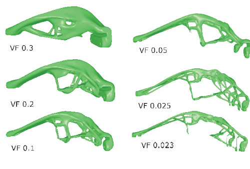
Configurations with VF 0.3, 0.2, 0.1 and 0.05 show progressively more slender members being developed, which form a cage-like structure around the payload region. The bolted support regions morph from a monolithic arrangement toward individual supports.
Configurations with VF 0.025 and 0.023 needed to be run at a very high mesh fidelity to be able to achieve continuous structure with a level of fineness. This is a very challenging problem for the optimizer. Coarser fidelity mesh, and a correspondingly chunkier structure will fail to find a continuous volume.
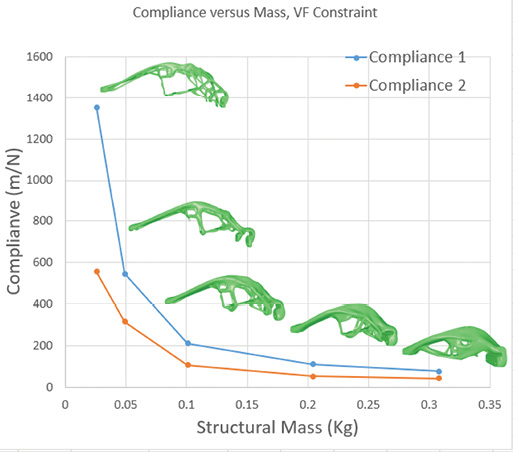
The structural mass is directly proportional to the VF. The payload mass of 0.44 kg remains constant. The two curves, blue (Compliance 1) and orange (Compliance 2), show the compliance of load case 1 (vertical 500 g) and load case 2 (lateral 500 g). Load case 1 dominates at all levels of VF. The relationship between mass and compliance is fairly linear up to around 0.1 F when the compliance rapidly increases with reduction in VF. The configuration changes from chunkier to finer at this point.
The influence of the inertia loading is interesting. The loads induced by the payload mass remain constant, but the loads due to structural mass are decreasing with a lower VF.
I also wanted to review the variation with peak stress for the various configurations. Fig. 7 shows the trend.
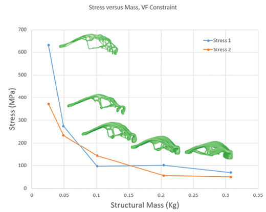
The stress quoted in the figure is the maximum throughout the structure for each load case. There is no constraint on stress for these configurations, so the value is a byproduct of the compliance-driven configuration. The smoothness of the stresses is surprising and is a testament to the smooth geometric surface fitted through the configuration. This point was confirmed when the resultant geometry was exported as a STEP file, imported into SolidWorks and analyzed using SolidWorks simulation.
The vertical load case is the dominant case for most of the configurations, apart from around VF of 0.1.
The maximum stress limit is assumed to be 300 MPa, later amended to 400 MPa. VF of 0.05 and above satisfy this requirement.
I also wanted to see the displacement trend, and this is shown in Fig. 8.

Fig. 8 shows a relatively small increase of maximum deflection with mass for both load cases up to a VF of 0.05. The deflection then rapidly increases, particularly for the vertical load case. The transition to the slender configuration gives high levels of deflection.
The lighter structures (VF 0.05 and below) seem to be much more deflection sensitive than stress sensitive. Not shown here was a further configuration of VF 0.23. This resulted in a 600% increase in deflection compared with VF 0.25, but only a 25% increase in stress. There is clearly a cliff-edge type effect on deflections around these slender configurations.
Lightweighted Generative Design Runs
Finally, I switch to the alternative optimization strategy of minimizing compliance, but with a stress constraint.
Based on the results so far it should be possible to target a stress constraint around 300 MPa and expect a mass of around 0.25 Kg (VF of 0.025). I ran this setting, and also a stress constraint of 400 MPa, which should be even lighter.
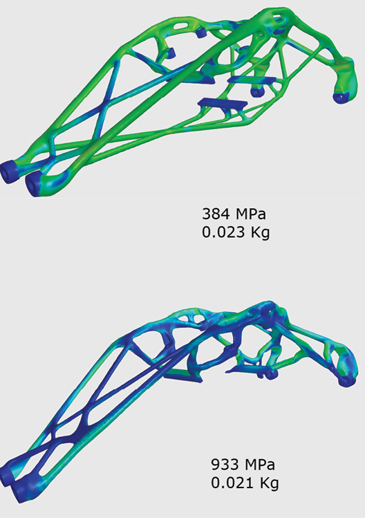
The two configurations are shown in Fig. 9.

The two configurations are different from the previous set, with no attempt to “cage in” the payload region. The comparison of mass and stress response is shown in Fig. 10.
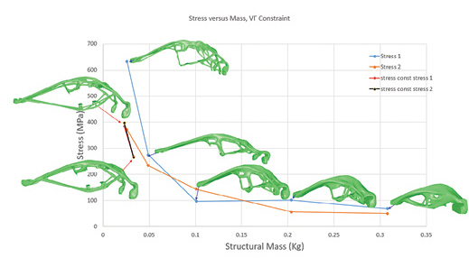
Fig. 10 shows that the target stresses of 300 MPa and 400 MPa can be achieved with a 0.033 Kg and a 0.023 Kg structure, respectively. These analyses had to be run with a very high-fidelity mesh. Both structures by definition are viable from a stress perspective, as opposed to the structures with no stress constraint seen previously. Stress responses without a stress constraint at 0.021 Kg reached 933 MPa. Fig. 11 shows the contrast in the two configurations.
The deflections are still high for the stress constrained analyses at 0.451 mm and 0.602 mm (0.033 kg and 0.023 kg). However, they are an improvement on the unconstrained analyses. It will be interesting to see if this can be tightened up once CogniCAD has displacement constraints available. In the meantime, if the compliance and displacements are known from a previous run, then compliance can be used as a constraint to control displacement. A stress of 400 MPa and compliance of 550 N mm is used, based on the trend shown in Fig. 6. This resulted in mass of 0.33 kg and a maximum deflection of 0.511 mm, which is an improvement on 0.602 mm.
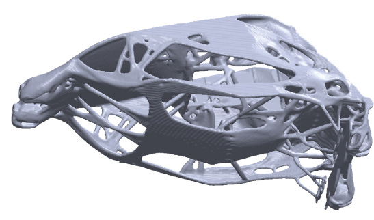
I also had a preview of the upcoming meso-design option, which allows for an organic cellular type design. The problem was run at a 0.1 VF level and the resulting design is shown in Fig. 12.
Conclusion
Setting up topology optimization problems is straightforward in CogniCAD. The ability to copy design studies within the cloud-based cabinet means that variations on VF, constraint type and so on were easily achieved. Once complete, each model can be reviewed independently within the cloud-based cabinet.
The optimizer was very successful in achieving smooth high-fidelity configurations at the very small, and hence challenging, Volume Fractions that this study drove toward. There was an expected big demand on computing resources.
I look forward to trying out future releases of CogniCAD with displacement and vibration constraints. I am also keen to explore the distributed meso-structure options due shortly.
Subscribe to our FREE magazine, FREE email newsletters or both!
About the Author
Tony Abbey is a consultant analyst with his own company, FETraining. He also works as training manager for NAFEMS, responsible for developing and implementing training classes, including e-learning classes. Send e-mail about this article to [email protected].
Follow DE

