In Pursuit of Predictable 3D Metal Printing
Simulation software offers promise in the desire for repeatable, standardized 3D metal prints.

Fig. 1: Multi-scale simulation of additive manufacturing processes promises to open the door for mass production of metal parts by delivering high precision and repeatable quality. Image courtesy of Siemens Digital Industries Software.


Latest News
April 15, 2020
Metal additive manufacturing (AM) stands poised to expand its footprint in the manufacturing sector, transitioning from a proven prototyping tool and small-lot fabrication process to mainstream part production. But there’s a catch.
Today’s AM technology isn’t predictable and repeatable enough to be cost-effective for companies that want to use AM to mass-produce parts. Currently, engineers must go through an iterative process of trying different printing parameters before they can identify the combination that will enable them to build parts that meet the necessary quality standards.
Technologists specializing in this area readily admit that reliance on trial-and-error makes 3D printing metal parts time-consuming and costly and hamstrings the technology with high failure rates.
“By some estimates, it takes companies five or more attempts to 3D print a qualified part from their additive manufacturing design models,” says Aaron Frankel, vice president of the additive manufacturing software program for Siemens Digital Industries Software.
“This high failure rate not only compromises the economic feasibility of additive, but it also thwarts efforts to employ the technology in high-volume production. This is particularly true of 3D metal printing,” he says.
The market, however, may have a solution. A growing variety of modeling and simulation tools aim to give engineers and designers the means to analyze the behavior of a part under a range of build conditions and provide the insight required to make “first-time-right printings” a reality (Fig. 1).
These tools provide an environment in which engineers can model and simulate multiple physical aspects, such as heat transfer and phase changes, as well as track the evolution of material properties throughout the build. In other words, the software supplies multi-scale, multiphysics capabilities that support the complex interaction of multiple algorithms and processes.
Consider Powder-Bed Systems
To understand the dynamic forces with which engineers and designers must contend, look at AM part manufacturing within the context of laser powder-bed fusion (LPBF) technology, one of the most common metal AM systems on the market today. These platforms owe their market presence to the technology’s superior ability to create geometrically complex parts.
In a typical LPBF process, a laser beam scans across a thin layer of metallic powders, fusing the desired cross-section of the geometry to the plate. After the initial exposure, the machine lowers the plate and applies the next layer of powder. The printer repeats these steps until the part is complete.
This process may be conceptually simple, but many dynamic and transient physical phenomena come into play, driven by the extremely high heating and cooling rates that occur.
For example, with these systems, the temperature of the melt pool determines the pool’s dynamics and stability. If the temperature falls within an unfavorable range, the build process can create conditions like partial vaporization of metallic powders, flow of molten metal, powder ejection and redistribution, rapid solidification and non-equilibrium phase transition.
These complex interactions can result in a product with a rough surface, significant porosity, residual stress and unfavorable phase and grain structures, with the consequent impact on properties. It is therefore important to understand the mechanisms responsible for defect formation.
Visibility Through Simulation
Almost all process conditions have an effect on the final as-built material quality. From the initial process conditions of powder humidity and size distribution, to the applied process parameters—such as powder thickness and laser power and speed—all of the factors play a role in defining the material’s microstructure.
Layer by layer, the heat source remelts the material several times, which intensifies the local thermal gradients’ history. Depending on the local evolution of the melt pool and the solidified microstructure, micro-defects such as hot cracking or porosities can occur. The evolution of those defects, combined with the part’s overall thermal history, lead to high residual stresses, distortions and various unexpected behaviors during printing.
To achieve the required visibility to mitigate or control these factors, engineers have turned to a special class of simulation. The challenge with the technology, however, becomes fitting simulation in the complete AM numerical chain within an acceptable cost for end users.
The most common solution is to simplify the physics that model the complete printing process. This promises to let engineers accurately predict the overall distortions and residual stresses arising during the building process, assess the print job’s manufacturability, and ensure topological part compliance with the initial design.
“It would probably be too ambitious to create a unique numerical model that simulates all of the physics to be considered, especially for an industrial application,” says Pierre-Adrien Pires, additive manufacturing domain leader at ESI Group. “The reasonable approach is to split our focus on several modeling scales, from the micro scale at melt pool size to the macro scale, where the complete part, its supports and the base plate are to be modeled.”
Starting Small
Simulating powder-bed build processes begins on the microscopic level. In this phase, engineers create micro-scale models of each particle, treating the particles as discrete entities. The goal here is to mitigate or avoid the effects of the microscopic defects.
For example, polycrystalline metallic alloys consist of individual crystallites, commonly referred to as grains. These grains are connected via grain boundaries, which are often formed through recrystallization and grain growth during metal part fabrication and heat treatment.
After the metal build process, most grains are connected through highly misoriented and equiaxed grain boundaries. Misoriented boundaries can influence the metal’s mechanical properties, such as high- and low-cycle fatigue lives, yield strength and creep. Equiaxed grain boundaries, on the other hand, can be susceptible to stress corrosion cracking, which can be undesirable in oil and gas, power generation, medical implant and aircraft engine applications.
Other types of grain boundaries, such as coincidence site lattice boundaries and low-angle boundaries, exhibit improved properties compared with equiaxed grain boundaries. The improved properties can include increased resistance to stress corrosion cracking by inhibiting intergranular cracking due to a disrupted network of the grain boundaries.
With this information, engineers can attempt to control grain structure, but this is not an easy task. “Grain structure control is challenging for metal AM,” says Rashid Miraj, director of technical operations at AlphaSTAR. “Grain structure optimization requires control of grain morphology, with grain size refinement, which can improve the mechanical properties of additive manufactured components. Here, influences of temperature gradient, solidification velocity and alloy composition on grain morphology come into play.”

In addition to grain structure issues, micro-scale analysis looks at the spreading (Fig. 2) and packing of the powder for different powder size distributions and roller speeds, directions (clockwise vs. counterclockwise) and configurations.
To do this, engineers use the discrete element modeling (DEM) method, which has become the main tool for computationally studying the micro-scale spreading process.
Research has shown that powder bed quality stands out as one of the main factors that influences manufactured part quality. One way to achieve optimum conditions is by simulating powder spreading, characterizing the interactions of individual metal powders with the substrate and container wall. This includes calculating the friction coefficients between the powders and boundaries.
AM technology developers have demonstrated that improving the powder bed density and homogeneity decreases melting defects like denudation and porosity and improves part quality. Therefore, engineers must understand the spreading process to accurately predict powder-bed quality.
Powder packing density also plays a critical role in the quality of the powder bed. This parameter directly affects powder thermal conductivity and consequently the temperature distribution in the melt pool. Engineers can model and simulate mechanical contact interactions between deformable particles using DEM software.
“Micro-scale simulations provide insights into the origin of defects such as porosity, lack of fusion, balling and surface roughness,” says Allyce Jackman, a CFD engineer at Flow Science. “These defects affect microstructure and part-scale structural integrity by compromising material strength. Porosity—which arises because of air being trapped within the material during melting—decreases the strength of the material in its solidified state. Lack of fusion, uneven surface roughness and balling defects make it difficult to evenly deposit subsequent layers, which leads to non-uniformity and reduced structural integrity in the overall part.”
The Intermediate Step
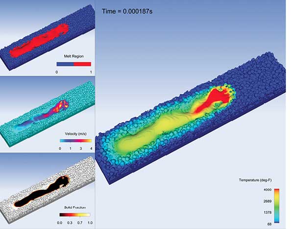
The next simulation chain segment occurs on the meso scale. Here, the simulation focuses on the laser’s interaction with the powder bed and on subsequent melting and solidification. At this scale, software tools simulate material deposition issues like powder-bed fusion, hydrodynamics in the melt pool and thermal stress (Fig. 3).
Meso-scale simulation helps engineers identify structural problems within the part. This level of simulation excels at analyzing the deposition path of a part to identify issues with the melt pool.

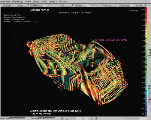
“It’s important to understand how the layer-by-layer 3D printing of a part can be affected by overheating, distortion, warping and re-coater collisions,” says Frankel. “Layer-by-layer simulation of the build process, however, is just one aspect of meso-level analysis. Engineers also need to be able to predict and correct defects caused by local overheating along each layer at the toolpath’s fusion point with the melt pool (Fig. 4).”
Looking at the bigger picture, meso-scale simulation examines the overall metallurgical properties of the build. Results depend on alloy composition, temperature distribution, deposition patterns and residual materials.
Because of their inherent qualities, meso-scale models interact with the micro and macro simulations of the powder-bed build. To help with this process, multi-scale, multiphysics simulation platforms use metallurgical tools and databases from established metal-based manufacturing tools to help generate results.
Simulation With a Wide Lens
Macro-scale simulation examines features such as part construction, distortions and stress buildup, and often rely on finite element analysis to provide insights into the build process (Fig. 5). Unlike the micro- and meso-scale simulations, this form of analysis ignores details of laser-particle interactions and fluid flow in the fusion zone, focusing instead on factors like temperature distribution, heat transfer and mechanical response.
Designers using macro-scale simulations can optimize the build orientation and subject the part to virtual service loads—environmental and structural—to ensure that it meets specification and performance requirements. These simulations also address factors like fatigue, aging and other degradation factors to assess as-is behavior and determine whether the virtual part will still meet specification later in its lifecycle.

Because the elements analyzed at this scale are larger in size, engineers can run the simulations fairly quickly. The simulations also promise precision. “Thermomechanical macro-scale models have proven to deliver high accuracy,” says Patrick Mehmert, product manager at Simufact. “Distortions and stresses can be predicted, and manufacturing risks like re-coater crashes or cracks can be identified.”
Simulations Pay It Forward
The simulations of each scale contribute valuable design and manufacturing information. Their contributions, however, extend beyond isolated scale concerns.
For example, micro- and meso-scale simulations provide engineers with information about process settings—such as laser power, scan speeds and scan patterns—which allows engineers to optimize melt pool dynamics and process stability. Once the process parameters are optimized, engineers can use the settings as input parameters for macro-scale simulations, like thermal stresses and distortions, to better understand the build quality.
“Optimizing the process parameters at the micro- and meso-scales ensures that the melt pool is of excellent quality,” says Paree Allu, senior CFD engineer at Flow Science. “This in turn paves the way for a good structural build.”
More Siemens Digital Industries Software Coverage
Subscribe to our FREE magazine, FREE email newsletters or both!
Latest News


